580 Series plug-in interface
Jump to navigation
Jump to search

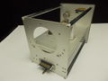
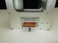
The plug-in interface of the 580-series scopes is a single 16-pin Amphenol 26-series connector.
An unusual aspect of the 580 Series plug-in interface is the transmission line termination scheme for the plug-in output signal. The output signal passes from the plug-in, through the plug-in interface connector, through the first of two distributed amplifiers in the 580-series mainframe's signal chain, and then back into the plug-in, which contains 93 Ω resistors to match the characteristic impedance of each side the balanced transmission line.
| Pin | Function | Comment |
|---|---|---|
| 1 | −150 V | R-C decoupled from mainframe |
| 2 | +100 V | R-C decoupled from mainframe |
| 3 | +225 V | R-C decoupled from mainframe |
| 4 | +350 V | R-C decoupled from mainframe |
| 5 | 6.3 VAC | heater supply from dedicated winding on mains transformer |
| 6 | 6.3 VAC | heater supply return for pin 5 |
| 7 | Alternate-trace sync pulse | from timebase |
| 8 | not connected | |
| 9 | +Vertical signal input | 93 Ω impedance |
| 10 | Ground | |
| 11 | −Vertical signal input | 93 Ω impedance |
| 12 | 117 VAC | from primary side of mains transformer |
| 13 | 117 VAC | return for pin 12 |
| 14 | +Vertical signal input return | 93 Ω, terminated and biased in plug-in, galvanically connected to pin 9 |
| 15 | +12.6 V | from regulated heater supply |
| 16 | −Vertical signal input return | 93 Ω, terminated and biased in plug-in, galvanically connected to pin 11 |
Pin group function legend
DC power and ground AC and heater power Deflection and Trigger Signals Control Signals
Used in
Scopes:
Plugins:
Pictures
-
Type 80 plug-in
-
Type 81A adapter plug-in

