432: Difference between revisions
No edit summary |
No edit summary |
||
| (24 intermediate revisions by 4 users not shown) | |||
| Line 1: | Line 1: | ||
{{Oscilloscope Sidebar | | {{Oscilloscope Sidebar | ||
|manufacturer=Tektronix | |||
summary=25 MHz dual trace portable scope | | |series=400-series scopes | ||
image=Tek 432 | |model=432 | ||
caption=Tektronix 432 | | |summary=25 MHz dual trace portable scope | ||
introduced=1971 | | |image=Tek 432 trace.jpg | ||
discontinued=(?) | | |caption=Tektronix 432 | ||
manuals= | |introduced=1971 | ||
* [ | |discontinued=(?) | ||
|manuals= | |||
* [[Media:070-1103-00.pdf|Tektronix 432 Manual]] | |||
* [[Media:070-1104-00.pdf|Tektronix 432 Operators Handbook]] | |||
* [[Media:Tek 432 and 434 fcp april 1972.pdf|Tektronix 432 and 434 Factory Calibration Procedure, April 1972]] | |||
}} | }} | ||
The '''Tektronix 432''' is a 25 MHz dual-trace portable solid-state oscilloscope. | The '''Tektronix 432''' is a 25 MHz dual-trace portable solid-state oscilloscope. | ||
| Line 13: | Line 17: | ||
There is also a rack-mount version, the R432. | There is also a rack-mount version, the R432. | ||
Each 432 vertical signal | Each 432 vertical signal path starts with the coupling switch, then a [[rotary cam attenuator]], then a dual-JFET source-follower | ||
then a [[rotary cam attenuator]], | buffer amp, then a [[155-0050-00]] differential amplifier (switched to [[155-0050-01]] after serial number B239999). | ||
then a dual-JFET source-follower buffer amp, | |||
then a [[155-0050-00]] differential amplifier (switched to [[155-0050-01]] after serial number B239999). | |||
The vertical and horizontal output amplifiers are fully discrete, using silicon bipolar transistors. | The vertical and horizontal output amplifiers are fully discrete, using silicon bipolar transistors. | ||
Triggering is done by a 4.7 mA [[ | Triggering is done by a 4.7 mA [[tunnel diode]] that is fed by a discrete trigger amplifier. | ||
The 432 consumes 55 watts maximum and weighs 20 pounds. | The 432 consumes 55 watts maximum and weighs 20 pounds. | ||
| Line 26: | Line 28: | ||
P31 [[phosphor]] was standard. P7 was also available. | P31 [[phosphor]] was standard. P7 was also available. | ||
== | {{MissingSpecs}} | ||
[[ | |||
==Links== | |||
* [[050-0674-00|Handle Replacement Modification Kit]] | |||
{{Documents|Link=432}} | |||
==Prices== | |||
{| class="wikitable" | |||
|- | |||
! Year | |||
! 1972 | |||
! 1973 | |||
|- | |||
! Catalog Price | |||
|align=right| $1,585 | |||
|align=right| $1,585 | |||
|- | |||
! In 2023 Dollars | |||
|align=right| $11,700 | |||
|align=right| $11,000 | |||
|} | |||
==Pictures== | ==Pictures== | ||
<gallery> | <gallery> | ||
Tek 432 1.jpg | |||
Tek 432 2.jpg | |||
Tek 432 3.jpg | |||
Tek_432_internal_1.jpg|This shows the area around the BNC input connectors for channels 1 and 2. This photo was taken when the owner was cleaning the vertical gain rotary switches which had become flaky after 45 years. | |||
This shows the area around the BNC input connectors for channels 1 and 2. | Tek_432_internal_2.jpg|View from the rear. The vertical gain attenuator switches are under the metal covers. | ||
Tek_432_internal_3.jpg|When the metal covers are removed, one can see the shaping/compensation capacitors. These can be unplugged, each one has 6 legs. | |||
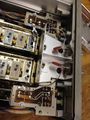
View from the rear. The vertical gain attenuator switches are under the metal covers. | Tek_432_internal_4.jpg|Another view of the shaping capacitors. Work on one channel at a time to avoid mixing these up. Carefully clean the legs with isopropal alcohol and paper towels. | ||
Tek_432_internal_5.jpg|In order to access the rotary gain switch fingers, one must first remove these BNC connectors, which means unsoldering the central wire (connects to a resistor/inductor feed-through) plus a debouce capacitor and lead going to the x1 x10 indicator lights. | |||
When the metal covers are removed, one can see the shaping/compensation capacitors. These can be unplugged, each one has 6 legs. | Tek_432_internal_6.jpg|Close up view of BNCs | ||
Tek_432_internal_7.jpg|Close up view of BNCs | |||
Another view of the shaping capacitors. Work on one channel at a time to avoid mixing these up. | Tek_432_internal_8.jpg|Close up view of BNCs. These need to be unsoldered for removal, but nothing else must be unsoldered to access/clean the vertical gain rotary switch. | ||
Tek_432_internal_9.jpg|View of the input preamp. This board needs to be unplugged only, but not removed or unsoldered. It has four 2-pin connectors. Then it can be removed, still attached to the compensation capacitor carriers. | |||
In order to access the rotary gain switch fingers, one must first remove these BNC connectors, which means unsoldering the central wire (connects to a resistor/inductor feed-through) plus a debouce capacitor and lead going to the x1 x10 indicator lights. | Tek_432_internal_10.jpg|Lifting off the assembly consisting of the 2 compensation capacitor carrier plus the vertical preamp board plus the push-button switch board for CH1/CHOP/ALTERNATE/CH2. The switch board has two plug connectors below that must be removed. It helps to have long fingers or a good pair of needle nose pliers. | ||
Tek_432_internal_11.jpg|Second view under the assembly being removed. | |||
Close up view of BNCs | Tek_432_internal_12.jpg|The rotary switches exposed. Each one has four contact fingers underneath. They are cleaned using small (5mm) wide strips of paper soaked in isopropanol alcohol (2-propanol). | ||
Tek_432_internal_13.jpg|One can just see the four contact fingers peeking out. You can get paper under them using small tweezers. Patience and calm are required. | |||
Close up view of BNCs | Tek_432_internal_14.jpg|A view of the variable-gain potentiometers. Note that the bodies are both cracked in the same place. Both had been noisy, but the noise was largely eliminated by sweeping them back and forth a dozen times. That may have scrubbed off the oxide. | ||
Tek_432_internal_15.jpg|A view of the contact fingers underneath the capacitor shaping blocks. Each channel has 8 NC and 8 NO fingers (the other half are on the bottom). These are easy to reach and clean as described. So each channel has a total of 20 contact fingers to clean. | |||
Close up view of BNCs. These need to be unsoldered for removal, but nothing else must be unsoldered to access/clean the vertical gain rotary switch. | |||
View of the input preamp. This board needs to be unplugged only, but not removed or unsoldered. It has four 2-pin connectors. Then it can be removed, still attached to the compensation capacitor carriers. | |||
Lifting off the assembly consisting of the 2 compensation capacitor carrier plus the vertical preamp board plus the push-button switch board for CH1/CHOP/ALTERNATE/CH2. The switch board has two plug connectors below that must be removed. It helps to have long fingers or a good pair of needle nose pliers. | |||
Second view under the assembly being removed. | |||
</gallery> | </gallery> | ||
==Components== | |||
{{Parts|432}} | |||
[[Category:400 series scopes]] | [[Category:400 series scopes]] | ||
[[Category:Specifications needed]] | [[Category:Specifications needed]] | ||
Latest revision as of 04:55, 11 March 2024

The Tektronix 432 is a 25 MHz dual-trace portable solid-state oscilloscope.
There is also a rack-mount version, the R432.
Each 432 vertical signal path starts with the coupling switch, then a rotary cam attenuator, then a dual-JFET source-follower buffer amp, then a 155-0050-00 differential amplifier (switched to 155-0050-01 after serial number B239999).
The vertical and horizontal output amplifiers are fully discrete, using silicon bipolar transistors.
Triggering is done by a 4.7 mA tunnel diode that is fed by a discrete trigger amplifier.
The 432 consumes 55 watts maximum and weighs 20 pounds.
P31 phosphor was standard. P7 was also available.
Key Specifications
- please add
Links
Documents Referencing 432
| Document | Class | Title | Authors | Year | Links |
|---|---|---|---|---|---|
| Tekscope 1972 V4 N5 Sep 1972.pdf | Article | Servicing the 432/434 Oscilloscopes | Ken Matheson | 1972 | 432 • 434 |
Prices
| Year | 1972 | 1973 |
|---|---|---|
| Catalog Price | $1,585 | $1,585 |
| In 2023 Dollars | $11,700 | $11,000 |
Pictures
-

-

-

-
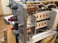
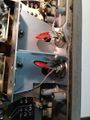
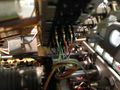
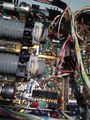
This shows the area around the BNC input connectors for channels 1 and 2. This photo was taken when the owner was cleaning the vertical gain rotary switches which had become flaky after 45 years.
-
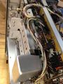
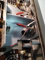
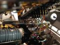
View from the rear. The vertical gain attenuator switches are under the metal covers.
-
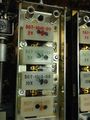
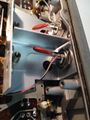
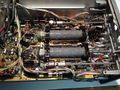
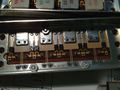
When the metal covers are removed, one can see the shaping/compensation capacitors. These can be unplugged, each one has 6 legs.
-

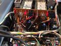
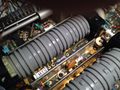
Another view of the shaping capacitors. Work on one channel at a time to avoid mixing these up. Carefully clean the legs with isopropal alcohol and paper towels.
-
In order to access the rotary gain switch fingers, one must first remove these BNC connectors, which means unsoldering the central wire (connects to a resistor/inductor feed-through) plus a debouce capacitor and lead going to the x1 x10 indicator lights.
-
Close up view of BNCs
-
Close up view of BNCs
-
Close up view of BNCs. These need to be unsoldered for removal, but nothing else must be unsoldered to access/clean the vertical gain rotary switch.
-
View of the input preamp. This board needs to be unplugged only, but not removed or unsoldered. It has four 2-pin connectors. Then it can be removed, still attached to the compensation capacitor carriers.
-
Lifting off the assembly consisting of the 2 compensation capacitor carrier plus the vertical preamp board plus the push-button switch board for CH1/CHOP/ALTERNATE/CH2. The switch board has two plug connectors below that must be removed. It helps to have long fingers or a good pair of needle nose pliers.
-
Second view under the assembly being removed.
-
The rotary switches exposed. Each one has four contact fingers underneath. They are cleaned using small (5mm) wide strips of paper soaked in isopropanol alcohol (2-propanol).
-
One can just see the four contact fingers peeking out. You can get paper under them using small tweezers. Patience and calm are required.
-
A view of the variable-gain potentiometers. Note that the bodies are both cracked in the same place. Both had been noisy, but the noise was largely eliminated by sweeping them back and forth a dozen times. That may have scrubbed off the oxide.
-
A view of the contact fingers underneath the capacitor shaping blocks. Each channel has 8 NC and 8 NO fingers (the other half are on the bottom). These are easy to reach and clean as described. So each channel has a total of 20 contact fingers to clean.


