4S2: Difference between revisions
No edit summary |
No edit summary |
||
| (44 intermediate revisions by 4 users not shown) | |||
| Line 1: | Line 1: | ||
The Tektronix 4S2 is a two-channel [[sampling oscilloscope|sampling]] vertical plug-in for the [[661]]. | {{Plugin Sidebar | ||
Signals enter the 4S2 through [[ | |manufacturer=Tektronix | ||
|series=661 | |||
|type=4S2 | |||
|summary=Dual channel sampling plugin | |||
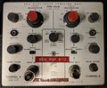
|image=4s2 3.jpg | |||
|caption=4S2 | |||
|introduced=1962 | |||
|discontinued=(?) | |||
|designers=George Frye; | |||
|manuals= | |||
* [[Media:070-356.pdf|Tektronix 4S2 Manual]] | |||
* [[Media:070-0536-00.pdf|Tektronix 4S2A Manual]] | |||
'''Calibration''' | |||
* [[Media:Tek 4s2 cal outline.pdf|Tektronix 4S2 Calibration Outline]] (OCR) | |||
* [https://w140.com/tek_fcp/tek_type_4s2_factory_cal_proc.pdf Tektronix 4S2 Field Recalibration Procedure] | |||
* [https://w140.com/tek_fcp/tek_type_4s2_tentative_factory_cal_proc.pdf Tektronix 4S2 Factory Calibration Procedure] | |||
* [[Media:tek_4s2a_eng_spec.pdf|Tektronix 4S2A Engineering Spec]] (OCR) | |||
}} | |||
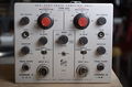
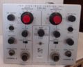
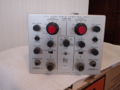
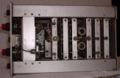
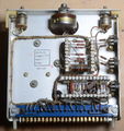
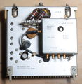
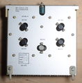
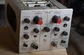
The '''Tektronix 4S2''' is a two-channel [[sampling oscilloscope|sampling]] vertical plug-in for the [[661]]. | |||
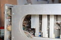
Signals enter the 4S2 through [[GR-874 connector]]s on the front panel. | |||
Unlike the [[4S1]], the 4S2's signal path does not contain a [[delay line]] between the input connector and the sampler. | |||
This has the advantage of maintaining higher pulse fidelity and thus higher bandwidth, but the disadvantage of making it impossible to see the leading edge of the triggering event unless a pre-trigger is used. | |||
The 4S2, which was designed in 1962, uses a four-diode sampling bridge. | |||
The 4S2A, designed in 1965, uses a two-diode sampling bridge. | |||
This design change is discussed in the 4S2A Engineering Spec document linked below. | |||
The 4S2 does not provide trigger pick-off. The 4S2A provides trigger pick-off for channel A. | |||
The 4S2 and 4S2A front panels look the same, but they use different GR-874 input connectors. | |||
The 4S2 uses a short airline unique to the 4S2. | |||
The 4S2A uses the connector-to-board system described in [[Patent US 3426311A|US Patent 3,426,311]] and has some parts in common with the [[3T7]]. | |||
{{BeginSpecs}} | |||
{{Spec | Bandwidth | DC to 3.9 GHz }} | |||
{{Spec | Rise time | 90 ps }} | |||
{{Spec | Deflection | 2 mV/Div to 200 mV/Div, 1−2−5 }} | |||
{{EndSpecs}} | |||
==See Also== | |||
* [[4S2 Pulser]] | |||
==Pictures== | |||
===4S2=== | |||
<gallery> | |||
Tek 4s2 front straight.jpg|4S2 | |||
4s2 3.jpg|4S2 | |||
4s2 2.jpg|4S2 | |||
4s2 1.jpg|4S2 | |||
4s2 4.jpg|4S2 | |||
Tek 4s2 avalanche pulse components.jpg|4S2 Pulse Generator | |||
Tek 4s2 avalanche pulse1.jpg|4S2 Pulse Generator | |||
Tek 4s2 avalanche pulse2.jpg|4S2 Pulse Generator | |||
Tek 4s2 avalanche pulse4.jpg|4S2 Pulse Generator | |||
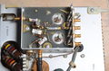
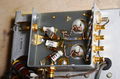
Tek 4s2 sampler.jpg|4S2 Sampler | |||
Tek 4s2 sampler2.jpg|4S2 Sampler | |||
Tek 4s2 ac amplifier outside.jpg|AC Amplifier | |||
Tek 4s2 ac amplifier components.jpg|AC Amplifier | |||
Tek 4s2 memory outside.jpg|Memory | |||
Tek 4s2 memory components.jpg|Memory | |||
Tek 4s2 inverter outside.jpg|Inverter | |||
Tek 4s2 inverter components.jpg|Inverter | |||
Tek 4s2 dual-trace outside.jpg|Dual Trace | |||
Tek 4s2 dual-trace components.jpg|Dual Trace | |||
Tek 4s2 left front inside.jpg|4S2 | |||
Tek 4s2 input connector.jpg|4S2 | |||
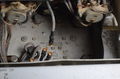
Tek 4s2 front right wiring.jpg|4S2 | |||
Tek 4s2 front 32.jpg|4S2 | |||
Tek 4s2 front bottom.jpg|4S2 | |||
Tek 4s2 bottom wiring.jpg|4S2 | |||
Tek 4s2 samplers.jpg|4S2 Samplers | |||
Tek 4s2 top cards.jpg|4S2 Top | |||
Tek 4s2 top front.jpg|4S2 Top Front | |||
Tek 4s2 top.jpg|4S2 Top | |||
Tek 4S2 var pots and pulse generator connections.jpg|Pulse Generator Card Removed, Var Gain Pots | |||
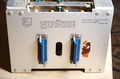
Tek 4s2 rear.jpg|4S2 Rear | |||
</gallery> | |||
===4S2A=== | |||
<gallery> | <gallery> | ||
Tek 4s2a front.jpg|4S2A Front | |||
Tek 4s2a sampler.png|42SA sampler schematic | |||
Tek 4s2a pulse gen.png|42SA pulse generator schematic | |||
Tek 4s2a pulse generator front.jpg|4S2A Pulse Generator Front | |||
Tek 4s2a pulse generator rear.jpg|4S2A Pulse Generator Rear | |||
Tek 4s2a gate board 2.jpg|4S2A Gate (Sampler) Board | |||
Tek 4s2a gate board.jpg | |||
Tek 661 4s2a 5t3 s-52.jpg|4S2A step response driven by [[S-52]]. 100 ps/div. | |||
</gallery> | </gallery> | ||
==Components== | |||
{{Parts|4S2}} | |||
{{Parts|4S2A}} | |||
[[Category:661 plugins]] | |||
[[Category:Sampling plugins]] | |||
[[Category:GR874]] | |||
Latest revision as of 09:21, 9 December 2023

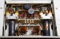
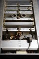
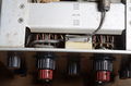
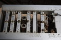
The Tektronix 4S2 is a two-channel sampling vertical plug-in for the 661. Signals enter the 4S2 through GR-874 connectors on the front panel.
Unlike the 4S1, the 4S2's signal path does not contain a delay line between the input connector and the sampler. This has the advantage of maintaining higher pulse fidelity and thus higher bandwidth, but the disadvantage of making it impossible to see the leading edge of the triggering event unless a pre-trigger is used.
The 4S2, which was designed in 1962, uses a four-diode sampling bridge. The 4S2A, designed in 1965, uses a two-diode sampling bridge. This design change is discussed in the 4S2A Engineering Spec document linked below. The 4S2 does not provide trigger pick-off. The 4S2A provides trigger pick-off for channel A.
The 4S2 and 4S2A front panels look the same, but they use different GR-874 input connectors. The 4S2 uses a short airline unique to the 4S2. The 4S2A uses the connector-to-board system described in US Patent 3,426,311 and has some parts in common with the 3T7.
Key Specifications
| Bandwidth | DC to 3.9 GHz |
|---|---|
| Rise time | 90 ps |
| Deflection | 2 mV/Div to 200 mV/Div, 1−2−5 |
See Also
Pictures
4S2
-
4S2
-
4S2
-
4S2
-
4S2
-
4S2
-
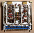
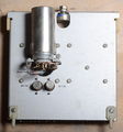
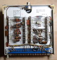
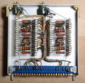
4S2 Pulse Generator
-
4S2 Pulse Generator
-
4S2 Pulse Generator
-
4S2 Pulse Generator
-
4S2 Sampler
-
4S2 Sampler
-
AC Amplifier
-
AC Amplifier
-
Memory
-
Memory
-

Inverter
-
Inverter
-
Dual Trace
-
Dual Trace
-
4S2
-
4S2
-
4S2
-
4S2
-
4S2
-
4S2
-
4S2 Samplers
-
4S2 Top
-
4S2 Top Front
-
4S2 Top
-
Pulse Generator Card Removed, Var Gain Pots
-
4S2 Rear


4S2A
-
4S2A Front
-
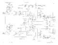
42SA sampler schematic
-
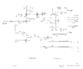
42SA pulse generator schematic
-
4S2A Pulse Generator Front
-
4S2A Pulse Generator Rear
-
4S2A Gate (Sampler) Board
-
-
4S2A step response driven by S-52. 100 ps/div.


Components
Some Parts Used in the 4S2
Some Parts Used in the 4S2A
| Part | Part Number(s) | Class | Description | Used in |
|---|---|---|---|---|
| 152-0252-00 | 152-0252-00 | Discrete component | Tek-made step recovery diode | 4S2A |
| 6688 | 154-0215-00 | Vacuum Tube (Pentode) | miniature high-slope VHF/UHF pentode | P80 • 3T77 • 3T77A • 4S2A • 526 • TR-4602 |
| 7308 | 154-0371-00 | Vacuum Tube (Dual Triode) | dual triode | 3S76 • 3S3 • 4S1 • 4S2A • 4S3 • S-311 |