7T11: Difference between revisions
m (-) |
No edit summary |
||
| (46 intermediate revisions by 5 users not shown) | |||
| Line 1: | Line 1: | ||
{{Plugin Sidebar| | {{Plugin Sidebar | ||
|manufacturer=Tektronix | |||
summary=Sampling Sweep Unit| | |series=7000-series scopes | ||
image= | |type=7T11 | ||
caption=Tektronix | |summary=Sampling Sweep Unit | ||
|image=7t11a.jpg | |||
|caption=Tektronix 7T11A sampling sweep unit | |||
|introduced=1969 | |||
manuals= | |discontinued=1990 | ||
* [ | |designers=George Frye;Al Zimmerman;Gene Cowan | ||
* [ | |manuals= | ||
* [ | * [[Media:070-0986-00.pdf|Tektronix 7T11 Manual]] (OCR) | ||
* [[Media:070-6176-00.pdf|Tektronix 7T11A Manual]] (OCR) | |||
* [[Media:7T11A Modification Insert.pdf|7T11A Modification - Manual Insert]] | |||
* [http://www.perdrix.co.uk/7T11Conversion/index.htm Dave Partridge's Report on Converting a Tektronix 7T11 to a 7T11A] | * [http://www.perdrix.co.uk/7T11Conversion/index.htm Dave Partridge's Report on Converting a Tektronix 7T11 to a 7T11A] | ||
}} | }} | ||
The '''Tektronix 7T11''' is a [[sampling oscilloscope|sampling]] time base plug-in for the [[7000-series scopes]] that was [[introduced in 1969]]. | |||
It is specially designed to work in conjunction with one or two [[7S11]] samplers and their [[7000_and_3S_series_sampling_heads|sampling head plug-ins]]. | |||
Because the 7T11 and 7S11 have [[7000-series Sampling Shoe|direct interconnections side by side]], they also work in slow mainframes. | |||
The 7T11 supports up to two 7S11 for dual channel or X–Y operation. | |||
It was designed by [[George Frye]], [[Al Zimmerman]], and [[Gene Cowan]]. | |||
{{BeginSpecs}} | |||
{{Spec | Sweep rate | 5 ms/Div to 10 ps/div in a 1−2−5 sequence. Variable speed-up ×2.5 on all ranges (i.e. down to 4 ps/Div) }} | |||
from | {{Spec | Time position Range | 50 ms to 50 ns in 10x steps. 50 ms to to 0.5 ms ranges are real time, 50 μs to 50 ns equivalent time sampling}} | ||
{{Spec | Time accuracy | 3%}} | |||
{{Spec | Trigger bandwidth | 500 MHz internal, 1 GHz from external trigger sources, 12.4 GHz in HF Sync mode }} | |||
{{Spec | Trigger sensitivity | | |||
* ×1 internal: 125 mV to 1 V<sub>p-p</sub>, 5 kHz to 500 MHz | |||
* ×10 internal: 12.5 mV to 1 V<sub>p-p</sub>, 5 kHz to 50 MHz | |||
* ×1 external 50 Ω: 12.5 mV to 2 V<sub>p-p</sub>, DC to 1 GHz | |||
* ×10 external 50 Ω: 1.25 mV to 2 V<sub>p-p</sub>, 1 kHz to 50 MHz | |||
* ×1 external 1 MΩ: 12.5 mV to 2 V<sub>p-p</sub>, DC to 100 MHz | |||
* ×10 external 1 MΩ: 1.25 mV to 2 V<sub>p-p</sub>, 1 kHz to 50 MHz | |||
* HF Sync mode: 10 mV to 500 mV<sub>p-p</sub> @ 1 GHz, 200 mV to 500 mV<sub>p-p</sub> @ 12.4 GHz | |||
}} | |||
{{Spec | Input impedance (Trig Input) | selectable, 1 MΩ / 50 Ω }} | |||
{{Spec | Max. input | | |||
* 1 MΩ: 100 V DC or P-P to 1 kHz, derate at −6 dB/octave above 1 kHz down to 5 V<sub>p-p</sub> | |||
* 50 Ω: 2 V (DC + peak AC) | |||
}} | |||
{{Spec | Jitter | | |||
* Sequential mode: < 10 ps at fastest sweep, < 0.4 Div otherwise | |||
* Random mode: < 30 ps at fastest sweep, 1 Div otherwise | |||
* HF Sync mode: < 20 ps with 12.4 GHz, 200 mV<sub>p-p</sub> signal | |||
}} | |||
{{EndSpecs}} | |||
==Links== | |||
* [https://www.amplifier.cd/Test_Equipment/Tektronix/Tektronix_7000_series_special/7T11A.htm Tek 7T11A page @ amplifier.cd] | |||
* [http://www.barrytech.com/tektronix/tek7000/tek7t11.html Tek 7T11 page @ barrytech.com] | |||
{{Documents|Link=7T11}} | |||
==Operation== | |||
Due to its sampling principle (so called equivalent time sampling or undersampling), the 7T11 can only be used on repetitive signals. | |||
Samples are always taken from signal portions delayed from the trigger event. | |||
This delay is adjustable on the front panel to select the portion of interest. | |||
At the three lowest time position ranges, the 7T11 changes from equivalent time sampling to real-time sampling. | |||
To obtain maximum bandwidth, the sampling heads contain no delay lines, so the 7T11 needs an external pre-trigger if there are random, | |||
high-jitter signals or if the original signal triggered onto needs to be observed. | |||
In the special case of a periodic signal with low jitter, a [[random sampling]] mode can be used so that the signal triggered on can be observed. | |||
In this case, an internal PLL locks to the signal and generates an internal pre-trigger. | |||
To display the triggering event without slowing the sweep rate enough to see the next pulse, the input signal can be delayed by an external delay line such as the [[7M11]]. | |||
X-Y operation is possible up to 14 GHz if one 7S11 resides in the A-horizontal slot of a 4-slot mainframe. | |||
Manual or external sweep is possible to connect a slow pen plotter through [[Pin Tip]] jacks located on the front panel. | |||
Additionally, there is an internal 200 MHz tunnel diode oscillator, which can be synchronized from external signals up to 14 GHz. | |||
This oscillator in turn drives a 10 MHz tunnel diode oscillator that provides the internal trigger signal. | |||
The 7T11 uses a [[BSM connector]] for pulse output on the front panel. | The 7T11 uses a [[BSM connector]] for pulse output on the front panel. | ||
== | Note that waveform acquisition with the 7T11 does not work in a [[7854]] mixed-mode scope because it uses the [[7000 Series plug-in interface|A1 sweep gate signal]] for blanking. | ||
The updated 7T11A does since it uses A17 for blanking. | |||
A 7T11 can be [http://www.perdrix.co.uk/7T11Conversion/index.htm field upgraded to 7T11A]. | |||
==Internals== | |||
The 7T11 makes use of 5 tunnel diodes in its triggering circuits: 2x [[152-0140-01]] (CR29 & CR142), 2x [[152-0177-00]] (CR134 & CR152) and 1x [[152-0329-00]] for the RF sync (CR28). | |||
==Pictures== | ==Pictures== | ||
<gallery> | <gallery> | ||
Tek 7t11 front.jpg | 7T11 front | |||
Tek 7t11 side connection.jpg | 7T11 [[7000-series_Sampling_Shoe|side connector]] | |||
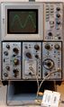
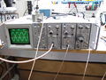
7s11-s4-7t11a-1ghz.jpg | 7T11A and [[7S11]] with [[S-4]] in a [[7613]] mainframe displaying a 1 GHz sine | |||
7t11a.jpg | 7T11A front | |||
Tek 7t11.jpg | | |||
Tek-7t11-right.jpg | Right view | |||
Tek-7t11-left.jpg | Left view | |||
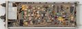
7t11-trigger.JPG | Trigger board in a 7T11 | |||
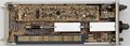
Tek-7t11-trigger-back.jpg | Back side of trigger board | |||
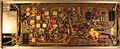
Tek-7t11-timing.jpg | Timing board in a 7T11 | |||
7t11-cr28.JPG | Tunnel Diode CR28 in a 7T11 | |||
7t11a-cr28.JPG | Tunnel Diode CR28 in a 7T11A | |||
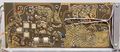
Tek-7t11-arming.jpg | Arming circuit detail (tunnel diodes CR142, CR152) | |||
Time-base-knob.jpg | Time base knob with sleeve insert | |||
</gallery> | |||
===Measurements=== | |||
<gallery> | |||
S6_8GHz.jpg | noisy 8 GHz taken with 7T11 and [[7S11]] + [[S-6]] in a [[7904]] | |||
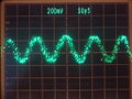
7s11-1ghz-norm.jpg | [[7S11]], 7T11, [[S-4]] displaying a 1 GHz sine (normal mode) | |||
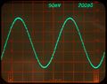
7s11-1ghz-smooth.jpg | 7S11, 7T11, S-4 displaying a 1 GHz sine (smooth mode) | |||
7s11-1ghz-smooth-store.jpg | 7S11, 7T11, S-4 displaying a 1 GHz sine (smooth mode, variable-persistence storage display of a [[7613]] mainframe) | |||
Tek 7633 7s11 7t11.jpg | Rackmount [[7633]] with two [[7S11]] and a 7T11 displaying a 2 GHz sinewave | |||
</gallery> | </gallery> | ||
==Components== | |||
{{Parts|7T11}} | |||
[[Category:7000 series horizontal plugins]] | [[Category:7000 series horizontal plugins]] | ||
[[Category: | [[Category:7000 series sampling plugins]] | ||
Latest revision as of 08:40, 4 December 2023

The Tektronix 7T11 is a sampling time base plug-in for the 7000-series scopes that was introduced in 1969. It is specially designed to work in conjunction with one or two 7S11 samplers and their sampling head plug-ins.
Because the 7T11 and 7S11 have direct interconnections side by side, they also work in slow mainframes. The 7T11 supports up to two 7S11 for dual channel or X–Y operation.
It was designed by George Frye, Al Zimmerman, and Gene Cowan.
Key Specifications
| Sweep rate | 5 ms/Div to 10 ps/div in a 1−2−5 sequence. Variable speed-up ×2.5 on all ranges (i.e. down to 4 ps/Div) |
|---|---|
| Time position Range | 50 ms to 50 ns in 10x steps. 50 ms to to 0.5 ms ranges are real time, 50 μs to 50 ns equivalent time sampling |
| Time accuracy | 3% |
| Trigger bandwidth | 500 MHz internal, 1 GHz from external trigger sources, 12.4 GHz in HF Sync mode |
| Trigger sensitivity |
|
| Input impedance (Trig Input) | selectable, 1 MΩ / 50 Ω |
| Max. input |
|
| Jitter |
|
Links
Documents Referencing 7T11
Operation
Due to its sampling principle (so called equivalent time sampling or undersampling), the 7T11 can only be used on repetitive signals. Samples are always taken from signal portions delayed from the trigger event. This delay is adjustable on the front panel to select the portion of interest. At the three lowest time position ranges, the 7T11 changes from equivalent time sampling to real-time sampling.
To obtain maximum bandwidth, the sampling heads contain no delay lines, so the 7T11 needs an external pre-trigger if there are random, high-jitter signals or if the original signal triggered onto needs to be observed. In the special case of a periodic signal with low jitter, a random sampling mode can be used so that the signal triggered on can be observed. In this case, an internal PLL locks to the signal and generates an internal pre-trigger.
To display the triggering event without slowing the sweep rate enough to see the next pulse, the input signal can be delayed by an external delay line such as the 7M11.
X-Y operation is possible up to 14 GHz if one 7S11 resides in the A-horizontal slot of a 4-slot mainframe.
Manual or external sweep is possible to connect a slow pen plotter through Pin Tip jacks located on the front panel.
Additionally, there is an internal 200 MHz tunnel diode oscillator, which can be synchronized from external signals up to 14 GHz. This oscillator in turn drives a 10 MHz tunnel diode oscillator that provides the internal trigger signal.
The 7T11 uses a BSM connector for pulse output on the front panel.
Note that waveform acquisition with the 7T11 does not work in a 7854 mixed-mode scope because it uses the A1 sweep gate signal for blanking. The updated 7T11A does since it uses A17 for blanking. A 7T11 can be field upgraded to 7T11A.
Internals
The 7T11 makes use of 5 tunnel diodes in its triggering circuits: 2x 152-0140-01 (CR29 & CR142), 2x 152-0177-00 (CR134 & CR152) and 1x 152-0329-00 for the RF sync (CR28).
Pictures
-
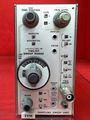
7T11 front
-

7T11 side connector
-
-
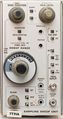
7T11A front
-
-
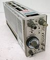
Right view
-
Left view
-
Trigger board in a 7T11
-
Back side of trigger board
-
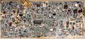
Timing board in a 7T11
-
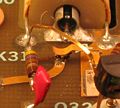
Tunnel Diode CR28 in a 7T11
-
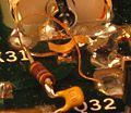
Tunnel Diode CR28 in a 7T11A
-
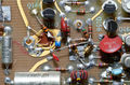
Arming circuit detail (tunnel diodes CR142, CR152)
-
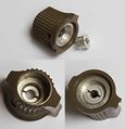
Time base knob with sleeve insert


Measurements
-
-
-

7S11, 7T11, S-4 displaying a 1 GHz sine (smooth mode)
-
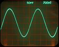
7S11, 7T11, S-4 displaying a 1 GHz sine (smooth mode, variable-persistence storage display of a 7613 mainframe)
-


Components
Some Parts Used in the 7T11
| Part | Part Number(s) | Class | Description | Used in |
|---|---|---|---|---|
| 155-0035-00 | 155-0035-00 • 155-0116-00 | Monolithic integrated circuit | quad op-amp | 3110 • 3S7 • 3T7 • 492 • 492A • 492AP • 492P • 494 • 494P • 496 • 496P • 4010 • 4011 • 4012 • 4013 • 7L5 • 7L12 • 7L13 • 7L14 • 7L18 • 7S11 • 7T11 • 7S12 • S-6 • 1461 • 4602 • P7001 • 613 • 653 |
| SMTD892 | 152-0329-00 | Discrete component | 19 mA, 1.5 pF tunnel diode | 284 • 7T11 • 7T11A |
| SMTD994 | 152-0177-01 | Discrete component | 10 mA, 2 pF tunnel diode | 067-0587-01 • 067-0580-00 • 3T5 • 3T6 • 485 • 5S14N • 7D14 • 7T11 • 7T11A • S-53 |
| SMTD995 | 152-0140-01 | Discrete component | 10 mA, 8 pF tunnel diode | 1S1 • 1S2 • 1502 • 21A • 22A • 3T5 • 3T6 • 475 • 475A • 475M • 544 • R544 • 546 • RM546 • 547 • RM547 • 556 • R556 • 581A • 585A • RM585 • 7B52 • 7B53N • 7B70 • 7B71 • 7D10 • 7D11 • 7T11 • 7T11A • R7912 • S-51 • S-52 • TU-5 • 067-0572-00 • 067-0572-01 • 067-0681-00 |
| STD962 | 152-0169-00 | Discrete component | 1 mA, 10 pF tunnel diode | L140 • Pentrix L20 • Pentrix L30 • 067-0518-00 • 067-0594-00 • 1L60 • 1S2 • 1503 • 3B5 • 3T7 • 4054 • 4054A • 4902 • 5S14N • 7S14 • 7T11 |