7A42: Difference between revisions
No edit summary |
|||
| (4 intermediate revisions by 2 users not shown) | |||
| Line 10: | Line 10: | ||
* [http://w140.com/tek_7a42_service1_ocr.pdf 7A42 Service Manual Volume 1 (PDF)] | * [http://w140.com/tek_7a42_service1_ocr.pdf 7A42 Service Manual Volume 1 (PDF)] | ||
* [http://w140.com/tek_7a42_service2_ocr.pdf 7A42 Service Manual Volume 2 (PDF)] | * [http://w140.com/tek_7a42_service2_ocr.pdf 7A42 Service Manual Volume 2 (PDF)] | ||
* [[Media:Tek 7a42 advanced triggering techniques.pdf | 7A42 Advanced Triggering Techniques]] | |||
}} | }} | ||
| Line 28: | Line 29: | ||
* 20 / 50 / 100 mV/Div (ECL mode) | * 20 / 50 / 100 mV/Div (ECL mode) | ||
* each direct or through 10:1 probe}} | * each direct or through 10:1 probe}} | ||
{{Spec | Input impedance | | {{Spec | Input impedance | 1 MΩ or 50 Ω}} | ||
{{Spec | Max. input voltage | | {{Spec | Max. input voltage | | ||
* at 1 MΩ: 25 V DC+peak AC below 36 MHz, down to | * at 1 MΩ: 25 V (DC+peak AC) below 36 MHz, down to 3 V<sub>AC</sub> at 300 MHz | ||
* at | * at 50 Ω: 5 V<sub>RMS</sub> during any 1 ms interval}} | ||
{{Spec | Trigger level | | {{Spec | Trigger level | | ||
* | * −1.27 to +1.28 V (TTL mode) in 10 mV steps | ||
* | * −254 mV to +256 mV (ECL mode) in 2 mV steps (or ×10)}} | ||
{{Spec | Hysteresis | 40 mV (TTL), 8 mV (ECL) (or ×10)}} | {{Spec | Hysteresis | 40 mV (TTL), 8 mV (ECL) (or ×10)}} | ||
{{Spec | Features | | {{Spec | Features | | ||
| Line 42: | Line 43: | ||
==Internals== | ==Internals== | ||
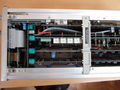
The 7A42's functions are controlled by an | The 7A42's functions are controlled by an [[Intel 8085]]A microprocessor. | ||
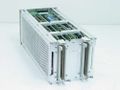
Each of the four input attenuator circuits contains five [[miniature relays]]. The bistable relay coils are wired in a 4x5 matrix. | Each of the four input attenuator circuits contains five [[miniature relays]]. The bistable relay coils are wired in a 4x5 matrix. | ||
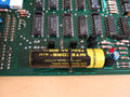
The 7A42 contains its own switch mode PSU, based on an SG3524 controller, that generates +5 V, | The 7A42 contains its own switch mode PSU, based on an SG3524 controller, that generates +5 V, −2 V and −5 V from the mainframe's ±50 V rails. | ||
==See Also== | |||
* [[067-1155-99]] | |||
* [[A6701]] | |||
* [[821]] | |||
==Pictures== | ==Pictures== | ||
| Line 68: | Line 74: | ||
Tek 7a42 fr11.jpg | amplifier board front - attenuators, amplifiers, channel switches | Tek 7a42 fr11.jpg | amplifier board front - attenuators, amplifiers, channel switches | ||
Tek 7a42 fr12.jpg | amplifier board rear - channel switches, two 15 ns delay lines | Tek 7a42 fr12.jpg | amplifier board rear - channel switches, two 15 ns delay lines | ||
Tek 7a42 11.jpg | |||
Tek 7a42 12.jpg | |||
Tek 7a42 13.jpg | |||
Tek 7a42 14.jpg | |||
Tek 7a42 15.jpg | |||
</gallery> | </gallery> | ||
[[Category:7000 series vertical plugins]] | [[Category:7000 series vertical plugins]] | ||
Revision as of 07:49, 19 June 2020
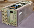
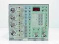
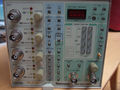
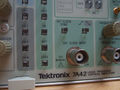
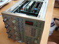
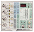
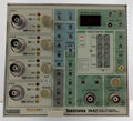
The Tektronix 7A42 is a four-channel 350 MHz plug-in for 7000-series scopes.
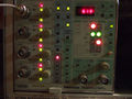
It was specifically designed for logic signals (TTL, ECL, CMOS) and supports triggering based on Boolean conditions of the four inputs.
A fifth trace, "Trigger View", displays the trigger function output or external clock input.
The input V/Div setting can only be seen in the mainframe's readout.
Tektronix recommended the P6131 10 MΩ probe, and the P6230 variable-offset 450 Ω probe for ECL circuits.
Key Specifications
| Bandwidth | 350 MHz |
|---|---|
| Deflection |
|
| Input impedance | 1 MΩ or 50 Ω |
| Max. input voltage |
|
| Trigger level |
|
| Hysteresis | 40 mV (TTL), 8 mV (ECL) (or ×10) |
| Features |
|
| Weight | 2.8 kg / 6.2 lb |
Internals
The 7A42's functions are controlled by an Intel 8085A microprocessor.
Each of the four input attenuator circuits contains five miniature relays. The bistable relay coils are wired in a 4x5 matrix.
The 7A42 contains its own switch mode PSU, based on an SG3524 controller, that generates +5 V, −2 V and −5 V from the mainframe's ±50 V rails.
See Also
Pictures
-
-

-
-
-

-
-
-
-
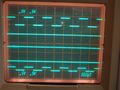
display - four signal traces plus trigger view
-
-
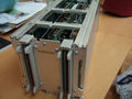
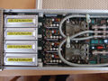
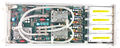
7A42 rear view
-
7A42 top view
-
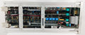
memory backup battery
-
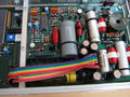
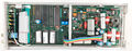
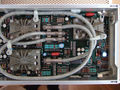
internal switch mode PSU for digital logic supplies
-
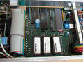
microprocessor board
-
amplifier board front - attenuators, amplifiers, channel switches
-
amplifier board rear - channel switches, two 15 ns delay lines
-
-
-
-
-