7A42

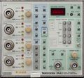
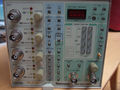
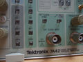
The Tektronix 7A42 is a four-channel 350 MHz plug-in for 7000-series scopes. It is a double-wide plug-in, designed by Kirk Wimmer.
Vertical:
- The 7A42 was specifically designed for logic signals (TTL, ECL, CMOS). It is not a Logic Analyzer however – the signal path and display is analog.
- The input V/div setting can only be seen in the mainframe's readout, and adapts automatically when a pin-coded ×10 probe is attached. (×100 probes are not supported and are incorrectly recognized as ×10.)
- A fifth trace, "Trigger View", displays the trigger function output or external clock input.
Triggering:
- The 7A42 supports triggering based on Boolean conditions of the four inputs.
- The trigger can be qualified by an external clock. A trigger filter control, variable from 0-300 ns, allows events shorter than the selected length to be suppressed. A TTL-level "reset" input will inhibit the trigger when active.
- There are two sets of trigger conditions, A and B, that can be individually selected or paired in an "A then B" mode called nested triggering, where the occurrence of condition A arms the trigger and condition B causes the trigger to be generated.
- The "A then B" interval gate signal can be routed to a counter for time measurement or event counting.
- Selected by an internal jumper, the front-panel trigger output can be configured for either the trigger signal, or the "A then B" interval
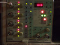
- The trigger level is set digitally for each channel, and shown on a 7-segment display. The trigger level display can also be used as a DVM to measure the offset voltage to which which an attached P6230 probe is set.
Mainframe Interface:
- Signal/Trigger outputs and mainframe readout use the left slot, allowing the 7A42 to be installed in the two center bays in a four-bay mainframe, together with another vertical plug-in in the left vertical bay.
- The right slot additionally provides the "A then B" interval gate on the trigger lines.
- There is a jumper to allow the readout to work in a 7854 mainframe.
Probes:
- Tektronix recommended the P6131, 300 MHz, 10 MΩ ×10 probe, and the P6230, 1.5 GHz, 450/50 Ω ×10, variable-offset probe for ECL circuits.
Key Specifications
| Bandwidth | 350 MHz in 7104, 300 MHz in 7904 |
|---|---|
| Deflection |
|
| Input impedance | 1 MΩ // 15 pF or 50 Ω |
| Max. input voltage |
|
| Trigger level |
|
| Trigger Hysteresis | 40/400 mV (TTL), 8/80 mV (ECL) |
| Features |
|
| Weight | 2.8 kg / 6.2 lb |
Links
The 067-1155-99 calibration fixture is specific to the 7A42.
Documents Referencing 7A42
| Document | Class | Title | Authors | Year | Links |
|---|---|---|---|---|---|
| 42W-5588.pdf | Application Note | Advanced Triggering Techniques | Roger Ensrud | 1984 | 7A42 • 7D11 • 7D15 |
Patents that may apply to 7A42
| Page | Title | Inventors | Filing date | Grant date | Links |
|---|---|---|---|---|---|
| Patent US 3584174A | Push-button switch apparatus having cam actuated switch contacts and selective illumination means | Tony Sprando • Peter S Winkelmann | 1969-06-09 | 1971-06-08 | Back-lit switches • 7A11 • 7A12 • 7A13 • 7A14 • 7A16 • 7A16P • 7A22 • 7A42 • 7B42N • 7B50 • 7B51 • 7B52 • 7B53A • 7B70 • 7B71 • 7B92 • 7B92A • 7D10 • 7D11 • 7D12 • 7D14 • 7D15 • 7D20 • 7F10 • 7L5 • 7L12 • 7L13 • 7L14 • 7L18 • 7M13 • 7S11 • 7S12 • 7T11 • 067-0587-00 • 067-0587-01 • 067-0587-02 • 067-0587-10 |
| Patent US 4513417A | Automatic processor restart circuit | James S. Lamb • Warren K. Wimmer | 1982-11-29 | 1985-04-23 | 7A42 |
| Patent US 4585975A | High speed Boolean logic trigger oscilloscope vertical amplifier with edge sensitivity and nested trigger | Warren K. Wimmer | 1983-04-21 | 1986-04-29 | 7A42 |
See also
Internals
The 7A42's functions are controlled by an Intel 8085A microprocessor, with code in three 2764 EPROMs (a fourth ROM socket is unused). The front-panel pushbuttons are handled by an Intel 8279 keyboard controller.
Each of the four 119-1517-00 input attenuator modules contains five 148-0145-00 miniature bi-stable relay actuators. These have four long pins plugging in to the base board, driving two solenoids that move a yoke which is held in the last active position by a permanent magnet. The yoke moves a pair of contact springs that directly short corresponding pads on the thick-film ceramic substrate. The relay coils are wired in a 4×5 matrix.
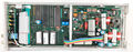
The 7A42 contains its own switch-mode PSU, based on an SG3524 controller, that generates +5 V, −2 V and −5 V from the mainframe's ±50 V rails.
There is a NiCd backup battery that allows the unit to retain its last configuration.
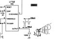
A 555 timer implements a 15 ms "real-time clock" and watchdog reset, another drives a beeper.
An internal jumper enables partial compatibility with a 7854 mainframe in storage mode (displaying any single channel, 1+2 in ALT, or 3+4 in ALT only). There are no restrictions with the 7854 in analog mode.
Pictures
-
-
-

-
-
-
-
-
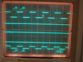
display - four signal traces plus trigger view
-
-
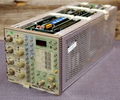
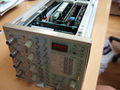
7A42 rear view
-
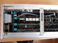
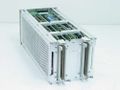
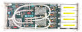
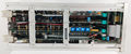
7A42 top view
-
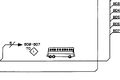
Schematic cartoon: Bus
-
Schematic cartoon: Chirp


Internal
-
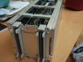
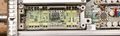
amplifier board (one attenuator cover removed)
-
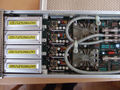
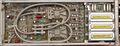
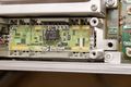
amplifier board front - attenuators, amplifiers, channel switches
-
amplifier board rear - channel switches, two 15 ns delay lines
-
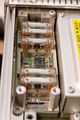
attenuator, cover removed
-

attenuator cover
-
attenuator, top
-
attenuator, one relay actuator removed
-
attenuator, all relay actuators removed
-
attenuator, all relay actuators removed
-
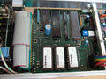
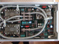
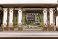
microprocessor board
-
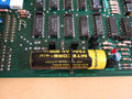
memory backup battery on microprocessor board replaced with LiIon
-
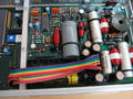
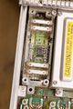
internal switch mode PSU for digital logic supplies
-
-
-


Components
Some Parts Used in the 7A42
| Part | Part Number(s) | Class | Description | Used in |
|---|---|---|---|---|
| 148-0145-00 | 148-0145-00 | Discrete component | miniature bi-stable relay actuator | 7A42 • 119-1517-00 |
| 155-0038-01 | 155-0038-00 • 155-0038-01 | Monolithic integrated circuit | 5-bit current source D/A converter | 7A42 • 7D13 • 7D14 • 7M13 • T4005 |
| 155-0078-00 | 155-0078-xx • 155-0273-00 • 155-0274-00 | Monolithic integrated circuit | broadband amplifier | 464 • 465 • 466 • 468 • 475 • 475A • 475M • 485 • 7834 • 7844 • 7854 • 7904 • R7903 • R7912 • 7912AD • 7912HB • 7104 • 7A16A • 7A16P • 7A24 • 7A26 • 7A42 • 067-0587-01 • 067-0680-00 • AM503 • PG502 • PG508 • DC510 • DC5010 • FG5010 |
| 155-0236-00 | 155-0236-00 | Hybrid integrated circuit | channel switch | 2445 • 2465 • 2467 • 7A42 |
| ICM7218 | 156-1621-00 • 156-1622-00 | Monolithic integrated circuit | 8-digit, 7-segment LED driver | 7A42 • SG5010 |
| Intel 8085A | 156-1088-00 | Monolithic integrated circuit | 8-bit microprocessor | 308 • 468 • 4025 • 7A42 • 7D02 • AFG5101 • AFG5102 • PFG5105 |
| Intel 8279 | 156-1535-00 | Monolithic integrated circuit | keyboard controller | 7A42 • AFG5101 • DM5010 • FG5010 • PFG5105 |
| SG3524 | 156-0933-00 • 156-0933-01 • 156-1585-00 • 156-1585-01 | Monolithic integrated circuit | PWM switch-mode controller | 067-1011-00 • 1502B • 1502C • 1503B • 1503C • 7A42 • DP100 |