535: Difference between revisions
No edit summary |
(Rearranged pictures) |
||
| (25 intermediate revisions by 6 users not shown) | |||
| Line 1: | Line 1: | ||
{{Oscilloscope Sidebar | | {{Oscilloscope Sidebar | | ||
title=Tektronix 535 | | title=Tektronix 535 | | ||
summary= | summary=10 (15) MHz dual-timebase scope | | ||
image=Tek-535a-crop.jpg | | image=Tek-535a-crop.jpg | | ||
caption=Tektronix 535A front | | caption=Tektronix 535A front | | ||
| Line 7: | Line 7: | ||
discontinued=1973 | | discontinued=1973 | | ||
manuals= | manuals= | ||
* [ | * [[Media:070-198.pdf | Tektronix 535 Manual (66 MB, PDF)]] | ||
* [ | * [[Media:070-0145-01.pdf | Tektronix 535A Manual (22 MB, OCR PDF)]] | ||
* [ | * [[Media:tek_type_535_545_operators_handbook.pdf|Tektronix 535 and 545 Operators Handbook (PDF, OCR)]] | ||
* [[Media:tek_type_535_modification_summary.pdf|Tektronix 535 Modification Summary (PDF, OCR, bad-OCR)]] | |||
* [[Media:navair_17-20aw-08_manual.pdf|Navair 17-20AW-08 Manual, which discusses the 535 (PDF, OCR)]] | |||
<small> | |||
* [ | '''Calibration''' | ||
* [ | |||
* [[Media:tek_type_535_fcp_low-sn.pdf|Tektronix 535 Factory Calibration Guide low-sn (PDF, OCR)]] | * [[Media:tek_type_535_fcp_low-sn.pdf|Tektronix 535 Factory Calibration Guide low-sn (PDF, OCR)]] | ||
* [[Media:tek_type_535_fcp_high-sn.pdf|Tektronix 535 Factory Calibration Guide high-sn (PDF, OCR)]] | * [[Media:tek_type_535_fcp_high-sn.pdf|Tektronix 535 Factory Calibration Guide high-sn (PDF, OCR)]] | ||
* [[Media:tek_type_535a_fcp.pdf|Tektronix 535A Factory Calibration Guide (PDF, OCR)]] | * [[Media:tek_type_535a_fcp.pdf|Tektronix 535A Factory Calibration Guide, August 1959 (PDF, OCR)]] | ||
* [[Media:Tek 535a fcp march 1968.pdf|Tektronix 535A Factory Calibration Procedure, March 1968 (PDF, needs OCR)]] | |||
</small> | |||
}} | }} | ||
The '''Tektronix Type 535''' is a | The '''Tektronix Type 535''' is a 10*/15 MHz oscilloscope that accepts [[letter-series and 1-series plug-ins]]. | ||
There are two timebases, and triggering is done with a Schmitt trigger made of a [[6U8]] tube (in | There are two timebases, and triggering is done with a Schmitt trigger made of a [[6U8]] tube (in | ||
| Line 68: | Line 65: | ||
{{BeginSpecs}} | {{BeginSpecs}} | ||
{{Spec | Bandwidth | DC to | {{SpecGroup | 535 SN 101-8627}} | ||
{{Spec | Rise time | 0. | {{Spec | Bandwidth | DC to 10 MHz (≤ 3 dB) with [[A|Type A plug-in]] }} | ||
{{Spec | Rise time | 0.035 μs }} | |||
{{SpecGroup | 535 SN 8268 up & 535A}} | |||
{{Spec | Bandwidth | DC to 15 MHz (≤ 3 dB) with [[K|Type K plug-in]] }} | |||
{{Spec | Rise time | 0.024 μs }} | |||
{{SpecGroup | all}} | |||
{{Spec | Line Voltage | 108/115/122/216/244 V<sub>AC</sub> ±10%,selected via primary voltage selector and voltage range selector switches, 50 Hz to 60 Hz. }} | {{Spec | Line Voltage | 108/115/122/216/244 V<sub>AC</sub> ±10%,selected via primary voltage selector and voltage range selector switches, 50 Hz to 60 Hz. }} | ||
{{Spec | Thermal Protection | Automatic resetting thermal cutout, in case internal temperature exceeds safe operating level }} | {{Spec | Thermal Protection | Automatic resetting thermal cutout, in case internal temperature exceeds safe operating level }} | ||
| Line 78: | Line 80: | ||
{{Spec | Screen Area | 6 cm × 10 cm}} | {{Spec | Screen Area | 6 cm × 10 cm}} | ||
{{Spec | Construction | Aluminum alloy chassis. Anodized front panel}} | {{Spec | Construction | Aluminum alloy chassis. Anodized front panel}} | ||
{{Spec | Weight| 65 lbs / 29,5 kg }} | |||
{{EndSpecs}} | {{EndSpecs}} | ||
==Special Models== | |||
Three "special models" of 535 were made: | |||
* 535-S1 (sweep delay 10 microseconds to 1 second) | |||
* 535-S2 (sweep delay 100 microseconds to 10 seconds) | |||
* 535-S6 (sweep delay 1.5 microseconds to 10 seconds) | |||
==Internals== | ==Internals== | ||
| Line 86: | Line 95: | ||
The 535's power supply provides regulated outputs of −150V, +100V, +225V, +350V, +500V as well as a +325 V unregulated output for CRT HV section. | The 535's power supply provides regulated outputs of −150V, +100V, +225V, +350V, +500V as well as a +325 V unregulated output for CRT HV section. | ||
The Power supply section is very similar to a [[549]]. It is | The Power supply section is very similar to a [[549]]. It is an all tube design using the following types | ||
[[5651]] as Voltage | [[5651]] as Voltage reference <br> | ||
[[12AX7]] as comparator<br> | [[12AX7]] as comparator <br> | ||
[[12B4]] as -150V | [[12B4]] as -150V series pass element<br> | ||
[[6080]] as +100V, +225V and +350V | [[6080]] as +100V, +225V and +350V series pass element<br> | ||
[[12B4]] as +500V | [[12B4]] as +500V series pass element<br> | ||
[[6AU6]] as error | [[6AU6]] as error amplifier for all rails<br> | ||
==Links== | ==Links== | ||
| Line 99: | Line 109: | ||
* [http://richardsears.wordpress.com/2011/06/18/tektronix-and-early-hewlett-packard/ Comparison of Tektronix 535, 535A, and HP 150A] with detailed pictures | * [http://richardsears.wordpress.com/2011/06/18/tektronix-and-early-hewlett-packard/ Comparison of Tektronix 535, 535A, and HP 150A] with detailed pictures | ||
* [http://www.lydecker.org/Tektronix_535A.htm Tektronix 535A - Restoring a Swap Meet Find] | * [http://www.lydecker.org/Tektronix_535A.htm Tektronix 535A - Restoring a Swap Meet Find] | ||
* [[120-086]] Power transformer schematic | |||
==Pictures== | ==Pictures== | ||
===535=== | |||
<gallery> | |||
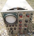
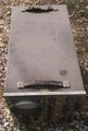
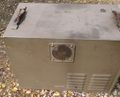
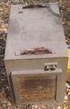
Tek 535 brown 1.jpg|535 with brown case | |||
Tek 535 brown 2.jpg|535 with brown case | |||
Tek 535 brown 3.jpg|535 with brown case | |||
Tek 535 brown 4.jpg|535 with brown case | |||
Tek 535 brown 5.jpg|535 with brown case | |||
</gallery> | |||
===535 S1=== | |||
<gallery> | <gallery> | ||
1.TEK535.JPG|535 S1 | 1.TEK535.JPG|535 S1 | ||
2.TEK535.JPG|535 S1 | 2.TEK535.JPG|535 S1 | ||
| Line 116: | Line 129: | ||
6.TEK535.JPG|535 S1 | 6.TEK535.JPG|535 S1 | ||
7.TEK535.JPG|535 S1 | 7.TEK535.JPG|535 S1 | ||
</gallery> | |||
===535 S2=== | |||
<gallery> | |||
Tek 535-s2 1.jpg|535-S2 | |||
Tek 535-s2 2.jpg|535-S2 | |||
Tek 535-s2 3.jpg|535-S2 | |||
</gallery> | |||
===535A=== | |||
<gallery> | |||
535A.jpg|535A | |||
535_vertical2.png|vertical amplifier | |||
Wellenkino 535a 3.jpg | |||
Wellenkino 535a 2.jpg | |||
Tek 535a delay line 1.jpg|535A delay line | |||
Tek 535a delay line 2.jpg|535A delay line | |||
Tek 535a trace.jpg|535A trace | |||
Tek 535a on plastic.jpg|535A | |||
</gallery> | |||
===RM35A=== | |||
<gallery> | |||
Tek rm35a 1.JPG | Tek rm35a 1.JPG | ||
Tek rm35a 2.jpg | Tek rm35a 2.jpg | ||
| Line 134: | Line 167: | ||
Tek rm35a 17.jpg | Tek rm35a 17.jpg | ||
Tek rm35a 18.jpg | Tek rm35a 18.jpg | ||
Rm35a front.jpg|R35A front | |||
Rm35a trig panel.jpg|R35A trigger controls | |||
Tek | Tek-RM35A-HV-Section.jpg | RM35A HV Section | ||
Tek | Tek-RM35A-A-Inten-B.jpg | RM35A B intensified by A Trace | ||
Tek | Tek-RM35A-Inside-Live.jpg |RM35A Internals | ||
Tek | Tek-RM35A-Live-Tubes.jpg |RM35A Internals | ||
Tek | Tek rm35a trace.jpg|RM35A trace | ||
Tek | Tek rm35a rear2.jpg|RM35A rear | ||
Tek | Tek rm35a rear.jpg|RM35A rear | ||
</gallery> | |||
===RM35AR=== | |||
<gallery> | |||
Tek rm35ar 1.jpg|RM35AR (mod 116B) | Tek rm35ar 1.jpg|RM35AR (mod 116B) | ||
Tek rm35ar 2.jpg|RM35AR (mod 116B) | Tek rm35ar 2.jpg|RM35AR (mod 116B) | ||
| Line 148: | Line 184: | ||
Tek rm35ar 4.jpg|RM35AR (mod 116B) | Tek rm35ar 4.jpg|RM35AR (mod 116B) | ||
Tek rm35ar 5.jpg|RM35AR (mod 116B) | Tek rm35ar 5.jpg|RM35AR (mod 116B) | ||
</gallery> | </gallery> | ||
[[Category:500 series scopes]] | [[Category:500 series scopes]] | ||
Revision as of 21:16, 2 January 2021

The Tektronix Type 535 is a 10*/15 MHz oscilloscope that accepts letter-series and 1-series plug-ins.
There are two timebases, and triggering is done with a Schmitt trigger made of a 6U8 tube (in early instruments) or a 6DJ8 tube (in late instruments). The delaying timebase on the 535 (non-A) supports delays up to 100 milliseconds. The 535-S1 supports delays up to 1 second. The 535A supports delays up to 10 seconds.
The 535 is functionally the same as a 545, but with a simpler, non-distributed vertical amplifier. Early 535s came in brown, square-cornered cabinets; in 1956 the cabinet became blue and round-cornered. Early 535s had selenium rectifiers. The 535 has a thermal cutoff.
Type 535, the single-timebase Type 531, and the first four plug-ins, Types 53A, 53B, 53C, and 53D, were introduced in August 1954, advertised as "... the «convertibles» of the Tektronix line". Types 541 and 545 came out in March 1955.
The 535's CRT is Tektronix part number 154-081.
In 1959, Types 531, 535, 541, and 545 were superseded by Types 531A, 535A, 541A, and 545A, which have more convenient controls. In addition, Types 531A and 535A have slightly faster (15 MHz vs. 11 MHz) vertical amplifiers.
There is a rack-mount version, Types RM35 and RM35A. Starting in 1963, the 535A was made with BNC connectors for the external trigger inputs. Prior to 1963, the external trigger inputs used UHF connectors. 1972 was the last year that any version of the 535 was sold. In 1973, the 54x series was still available, but nothing from the 53x series.
The first 535s had brown slide-out cases, then blue slide-out cases, and finally blue cases with pop-off sides.
From the October 1959 issue of TekScope:
In Type 535 and 545 the total delaying sweep time is limited to 10 ms/cm. If a total delaying sweep time in excess of 10 ms/cm is required, a K535-S1 modification kit (Tek #040-063) which gives a maximum delay sweep range of 1 s/cm. This kit is available for $40.00 in including a new front panel.
* With Type A or B plug-in; 11 MHz with Type K or other fast plug-in.
Key Specifications
| — 535 SN 101-8627 — | |
| Bandwidth | DC to 10 MHz (≤ 3 dB) with Type A plug-in |
| Rise time | 0.035 μs |
| — 535 SN 8268 up & 535A — | |
| Bandwidth | DC to 15 MHz (≤ 3 dB) with Type K plug-in |
| Rise time | 0.024 μs |
| — all — | |
| Line Voltage | 108/115/122/216/244 VAC ±10%,selected via primary voltage selector and voltage range selector switches, 50 Hz to 60 Hz. |
| Thermal Protection | Automatic resetting thermal cutout, in case internal temperature exceeds safe operating level |
| Power Consumption | 500 W with Type CA plug-in |
| Cooling | AC Fan |
| Trigger Modes | AC/DC/AC LF Reject, and HF Sync |
| Anode Potential | 10 kV |
| Screen Area | 6 cm × 10 cm |
| Construction | Aluminum alloy chassis. Anodized front panel |
| Weight | 65 lbs / 29,5 kg |
Special Models
Three "special models" of 535 were made:
- 535-S1 (sweep delay 10 microseconds to 1 second)
- 535-S2 (sweep delay 100 microseconds to 10 seconds)
- 535-S6 (sweep delay 1.5 microseconds to 10 seconds)
Internals
Power Supply
The 535's power supply provides regulated outputs of −150V, +100V, +225V, +350V, +500V as well as a +325 V unregulated output for CRT HV section.
The Power supply section is very similar to a 549. It is an all tube design using the following types
5651 as Voltage reference
12AX7 as comparator
12B4 as -150V series pass element
6080 as +100V, +225V and +350V series pass element
12B4 as +500V series pass element
6AU6 as error amplifier for all rails
Links
- Comparison of Tektronix 535, 535A, and HP 150A with detailed pictures
- Tektronix 535A - Restoring a Swap Meet Find
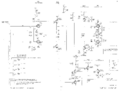
- 120-086 Power transformer schematic
Pictures
535
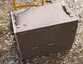
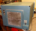
-
535 with brown case
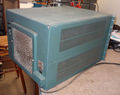
-
535 with brown case
-
535 with brown case
-
535 with brown case
-
535 with brown case


535 S1
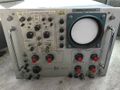
-
535 S1
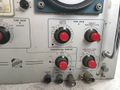
-
535 S1
-
535 S1
-
535 S1
-
535 S1
-

535 S1
-
535 S1


535 S2
-
535-S2
-
535-S2
-
535-S2


535A
-
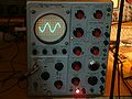
535A
-
vertical amplifier
-
-
-
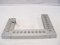
535A delay line
-
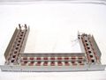
535A delay line
-

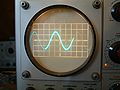
535A trace
-
535A


RM35A
-
-
-
-
-
-
-
-
-
-
-
-
-
-
-
-
-
-
-
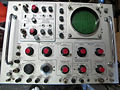
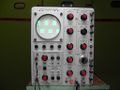
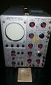
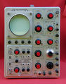
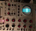
R35A front
-
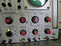
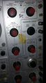
R35A trigger controls
-
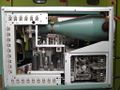
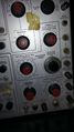
RM35A HV Section
-
RM35A B intensified by A Trace
-
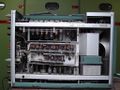
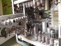
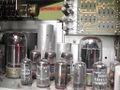
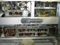
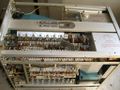
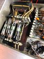
RM35A Internals
-

RM35A Internals
-

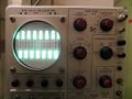
RM35A trace
-
RM35A rear
-
RM35A rear


RM35AR
-
RM35AR (mod 116B)
-
RM35AR (mod 116B)
-
RM35AR (mod 116B)
-

RM35AR (mod 116B)
-
RM35AR (mod 116B)


