280: Difference between revisions
No edit summary |
No edit summary |
||
| (13 intermediate revisions by 4 users not shown) | |||
| Line 1: | Line 1: | ||
The Tektronix Type 280 Trigger Countdown Unit takes in a signal with repetition rate | {{Instrument Sidebar | ||
and puts out a pulse train with repetition rate in the 15 to 45 MHz range | |manufacturer=Tektronix | ||
|model=280 | |||
|class=Accessory | |||
|series= | |||
|summary=Trigger Countdown Unit | |||
|image=Tek_type_280_1.jpg | |||
|caption=Tek Type 280 | |||
trigger point in the | |introduced=1963 | ||
|discontinued=(?) | |||
|designers= | |||
|manuals= | |||
* [[Media:070-350.pdf|Tektronix 280 Manual]] | |||
}} | |||
The '''Tektronix Type 280 Trigger Countdown Unit''' takes in a signal with repetition rate between 50 MHz and 5 GHz, and puts out a pulse train with repetition rate in the 15 to 45 MHz range whose leading edges are synchronized with a particular trigger point in the input signal. | |||
The main purpose of the 280 is to extend the frequency range of the trigger circuitry in sampling scopes. | |||
For example, consider a scope with a [[3T77]] and a [[3S2]] with [[S-2]] sampling heads. | |||
The S-2 has response to at least 4 GHz but the [[3T77]] is only rated to trigger up to 300 MHz, so the setup cannot, for example, be used to observe a 2 GHz sinewave. | |||
By using a Type 280, the 2 GHz sinewave can be fed to the Type 280, which will produce 15 to 45 MHz pulses that can be fed to the 3T77, which will easily trigger. | |||
The main concern with a setup like this is jitter. The 3T77 is rated at 50 ps jitter. | |||
The presence of the 280 does nothing to help the jitter of 3T77, so that becomes the limiting factor. | |||
Assuming that for a clear display, the triggering jitter must be less than 10% of the period of the observed signal, this gives a minimum signal period of 500 ps (2 GHz). | |||
The 280 thus extends the top of frequency range of the system from 300 MHz to 2 GHz. | |||
This was very useful with a [[661]] with a [[4S2|4S2A]] and a [[5T1]] as the 5T1's maximum triggering frequency is 1 GHz and it has 30 ps of jitter but the 4S2A's frequency response extends to 3.5 GHz. | |||
Without the 280, the maximum sinewave frequency that can be observed is 1 GHz; with the 280 it is 3.5 GHz. | |||
Later timing plug-ins like the [[5T3]] include built-in synchronizing circuits that eliminate the need for the countdown units such as the 280. | |||
Signal connections on the 280 use [[GR-874 connector]]s. The trigger circuit is built around a [[152-0099-00|50 mA (152-099)]] [[tunnel diode]]. | |||
==Pictures== | |||
<gallery> | <gallery> | ||
Tek 280.jpg|Photo | |||
Tek 280 schem.png|Schematic | |||
Tek type 280 1.jpg | |||
Tek type 280 2.jpg | |||
Tek type 280 3.jpg | |||
Tek type 280 4.jpg | |||
Tek type 280 5.jpg | |||
Tek type 280 6.jpg | |||
</gallery> | </gallery> | ||
{{Parts|280}} | |||
[[Category:GR874]] | |||
Latest revision as of 02:07, 13 November 2022
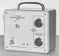
The Tektronix Type 280 Trigger Countdown Unit takes in a signal with repetition rate between 50 MHz and 5 GHz, and puts out a pulse train with repetition rate in the 15 to 45 MHz range whose leading edges are synchronized with a particular trigger point in the input signal.
The main purpose of the 280 is to extend the frequency range of the trigger circuitry in sampling scopes. For example, consider a scope with a 3T77 and a 3S2 with S-2 sampling heads. The S-2 has response to at least 4 GHz but the 3T77 is only rated to trigger up to 300 MHz, so the setup cannot, for example, be used to observe a 2 GHz sinewave.
By using a Type 280, the 2 GHz sinewave can be fed to the Type 280, which will produce 15 to 45 MHz pulses that can be fed to the 3T77, which will easily trigger.
The main concern with a setup like this is jitter. The 3T77 is rated at 50 ps jitter. The presence of the 280 does nothing to help the jitter of 3T77, so that becomes the limiting factor. Assuming that for a clear display, the triggering jitter must be less than 10% of the period of the observed signal, this gives a minimum signal period of 500 ps (2 GHz).
The 280 thus extends the top of frequency range of the system from 300 MHz to 2 GHz. This was very useful with a 661 with a 4S2A and a 5T1 as the 5T1's maximum triggering frequency is 1 GHz and it has 30 ps of jitter but the 4S2A's frequency response extends to 3.5 GHz. Without the 280, the maximum sinewave frequency that can be observed is 1 GHz; with the 280 it is 3.5 GHz.
Later timing plug-ins like the 5T3 include built-in synchronizing circuits that eliminate the need for the countdown units such as the 280.
Signal connections on the 280 use GR-874 connectors. The trigger circuit is built around a 50 mA (152-099) tunnel diode.
Pictures
-
Photo
-
Schematic
-
-
-
-
-
-
Some Parts Used in the 280
| Part | Part Number(s) | Class | Description | Used in |
|---|---|---|---|---|
| 120-0290-00 | 120-0290-00 | Discrete component | power transformer | 280 |
| SMTD907 | 152-0275-00 | Discrete component | 50 mA, 5 pF germanium tunnel diode | 280 • 661 |
| TD1081 | 152-0099-00 • 152-0334-00 | Discrete component | 50 mA, 6 pF germanium tunnel diode | 280 • 661 • 017-0086-00 |


