560-series scopes: Difference between revisions
(→560 series scopes: img) |
mNo edit summary |
||
| (25 intermediate revisions by 4 users not shown) | |||
| Line 1: | Line 1: | ||
The 560 series | The '''Tektronix 560 series''' of mainframes includes the [[560]], [[506]], [[561]], [[564]], [[565]], [[567]], and [[568]]. | ||
They were introduced with the [[560]] and [[561]] in 1961. The 560 series has plug-ins that drive the CRT deflection plates directly. | |||
<gallery widths="150" heights="180"> | <gallery widths="150" heights="180"> | ||
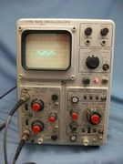
Tek 506 331023143159.jpg | '''[[506|506 − 20 MHz mainframe]]''' (1964) | |||
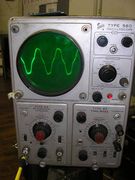
Tek 560 1.jpeg | '''[[560|560 − Basic mainframe]]''' (1961) | |||
Tek 561s.jpg | '''[[561]]''' (1961) | |||
Tek rm561.jpg | '''[[RM561|RM561 − Rack-mount 561]]''' | |||
561a-2.jpg | '''[[561A]]''' (1962) | |||
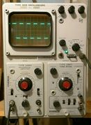
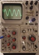
Tek_561b_cal_trace.jpg | '''[[561B|561B − Solid state scope]]''' (1969) | |||
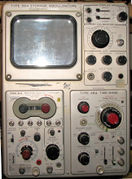
Tek564 front.jpg | '''[[564|564 − Storage scope]]''' (1962−1968?) | |||
R564B 1.JPG | '''[[RM564|RM564 − Storage scope]]''' (1962−1968?) | |||
Tek564b-3a3-3b3.jpg | '''[[564B|564B − Solid state storage scope]]''' (1968) | |||
Tek565-crop.jpg | '''[[565|565 − Dual-beam scope]]''', two plug-ins; built-in trigger, sweep, and horizontal amplifier (1963) | |||
567 front.jpg | '''[[567|567 − Sampling scope with digital readout]]''' (1962) | |||
568_1.JPG | '''[[568|568 − Sampling scope]]''' (1967) | |||
</gallery> | </gallery> | ||
Early 560-series mainframes (e.g., the [[561]]) had tubes in the low voltage power supply and in the high voltage power supply. | |||
Later scopes in the series (e.g., the [[561|561B]], the [[564|564B]], and [[568]]) were all solid state except for the CRT. | |||
==Common Features== | |||
* They accept [[560-series plug-ins]] (the 567 additionally accepts the [[6R1]] or [[6R1A]] plug-ins) | |||
* The [[560 Series plug-in interface]] is designed so that the plug-ins drive the CRT vertical and horizontal deflection plates directly (exception: the 565, which includes built-in trigger, timebase, and horizontal amplifier circuitry) | |||
* They don't contain a vertical [[delay line]] (some plug-ins, e.g., the [[3A6]] have built-in delay lines so the rising edge of fast pulses with low repetition rate can be seen) | |||
* They have linear power supplies (exception: the 560 power supply is basically a switch-mode power supply) | |||
* They don't use post-deflection acceleration of the CRT beam | |||
==Plug-ins== | |||
[[560-series plug-ins]] includes the 2-series models (e.g., the [[2A60]] and [[2B67]]) | |||
and the later 3-series models (e.g., the [[3A1]] and [[3B3]]) which consume more power than the | |||
power supply in the 560 and 561 can deliver (the 561A can meet the current demands of 3-series plug-ins). | |||
'''Advantages of plug-ins driving the CRT directly''' | |||
* Lower cost for an entry-level configuration. No need for expensive high-speed amplifiers anywhere in the system. | |||
* Bandwidth can be upgraded later by adding faster plug-ins. | |||
* Replacing plug-ins has a high likelihood of fixing problems, unless there is a problem in the power supply or CRT. | |||
* A small number of mainframe models can support a wide range of applications. | |||
'''Disadvantages of plug-ins driving the CRT directly''' | |||
* Checking calibration after changing plug-ins is recommended. | |||
The signal path of the plug-in to mainframe interface is not as well standardized as it is on [[500-series scopes]] or [[7000-series scopes]]. This is primarily due to variability in deflection sensitivity of CRTs. The 564B manual says:<blockquote> | |||
The accuracy of measurements made with the Type 564B depends on the calibration of the plug-in units used. | |||
Since the plug-in units drive the deflection plated directly, each unit must be adjusted to match the deflection sensitivity of the particular CRT it drives. | |||
Therefore, the gain or sweep timing adjustment must be checked each time a plug-in unit is changed. | |||
On most units, gain or timing calibration is made with a front-panel screwdriver adjustment. | |||
</blockquote> | |||
* Since each plug-in contains deflection amplifiers, 560-series plug-ins cost more than a plug-in with equivalent functionality for a mainframe that has built-in deflection amplifiers. The purchase cost, weight, and maintenance burden of the extra deflection amplifiers adds up, particularly if the customer wants several different plug-ins at the high-speed end of the 560-series range. | |||
[[Category:Visual index pages]] | [[Category:Visual index pages]] | ||
[[Category:Introduced in 1961]] | [[Category:Introduced in 1961]] | ||
Latest revision as of 22:00, 2 December 2023
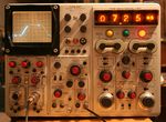
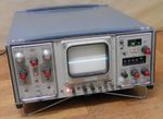
The Tektronix 560 series of mainframes includes the 560, 506, 561, 564, 565, 567, and 568. They were introduced with the 560 and 561 in 1961. The 560 series has plug-ins that drive the CRT deflection plates directly.
-
506 − 20 MHz mainframe (1964)
-
560 − Basic mainframe (1961)
-
561 (1961)
-
561A (1962)
-
561B − Solid state scope (1969)
-
564 − Storage scope (1962−1968?)
-
RM564 − Storage scope (1962−1968?)
-
565 − Dual-beam scope, two plug-ins; built-in trigger, sweep, and horizontal amplifier (1963)
-
568 − Sampling scope (1967)
Early 560-series mainframes (e.g., the 561) had tubes in the low voltage power supply and in the high voltage power supply. Later scopes in the series (e.g., the 561B, the 564B, and 568) were all solid state except for the CRT.
Common Features
- They accept 560-series plug-ins (the 567 additionally accepts the 6R1 or 6R1A plug-ins)
- The 560 Series plug-in interface is designed so that the plug-ins drive the CRT vertical and horizontal deflection plates directly (exception: the 565, which includes built-in trigger, timebase, and horizontal amplifier circuitry)
- They don't contain a vertical delay line (some plug-ins, e.g., the 3A6 have built-in delay lines so the rising edge of fast pulses with low repetition rate can be seen)
- They have linear power supplies (exception: the 560 power supply is basically a switch-mode power supply)
- They don't use post-deflection acceleration of the CRT beam
Plug-ins
560-series plug-ins includes the 2-series models (e.g., the 2A60 and 2B67) and the later 3-series models (e.g., the 3A1 and 3B3) which consume more power than the power supply in the 560 and 561 can deliver (the 561A can meet the current demands of 3-series plug-ins).
Advantages of plug-ins driving the CRT directly
- Lower cost for an entry-level configuration. No need for expensive high-speed amplifiers anywhere in the system.
- Bandwidth can be upgraded later by adding faster plug-ins.
- Replacing plug-ins has a high likelihood of fixing problems, unless there is a problem in the power supply or CRT.
- A small number of mainframe models can support a wide range of applications.
Disadvantages of plug-ins driving the CRT directly
- Checking calibration after changing plug-ins is recommended.
The signal path of the plug-in to mainframe interface is not as well standardized as it is on 500-series scopes or 7000-series scopes. This is primarily due to variability in deflection sensitivity of CRTs. The 564B manual says:
The accuracy of measurements made with the Type 564B depends on the calibration of the plug-in units used. Since the plug-in units drive the deflection plated directly, each unit must be adjusted to match the deflection sensitivity of the particular CRT it drives. Therefore, the gain or sweep timing adjustment must be checked each time a plug-in unit is changed. On most units, gain or timing calibration is made with a front-panel screwdriver adjustment.
- Since each plug-in contains deflection amplifiers, 560-series plug-ins cost more than a plug-in with equivalent functionality for a mainframe that has built-in deflection amplifiers. The purchase cost, weight, and maintenance burden of the extra deflection amplifiers adds up, particularly if the customer wants several different plug-ins at the high-speed end of the 560-series range.

