1405: Difference between revisions
Jump to navigation
Jump to search
(cat) |
No edit summary |
||
| (15 intermediate revisions by 2 users not shown) | |||
| Line 1: | Line 1: | ||
The Tektronix 1405 TV Sideband | {{Instrument Sidebar | ||
|manufacturer=Tektronix | |||
|model=1405 | |||
|class=Audio/Video | |||
|series= | |||
|summary=TV sideband adapter | |||
|image=Tek 1405 front 2.jpg | |||
|caption=Tektronix 1405 | |||
|introduced=1976 | |||
|discontinued=(?) | |||
|manuals= | |||
* [[Media:070-2078-00.pdf|Tektronix 1405 Manual]] | |||
* [[Media:Tek_1405_instructions.pdf|Tektronix 1405 Instructions]] | |||
}} | |||
The '''Tektronix 1405 TV Sideband Adapter''' is a signal generator used with a spectrum analyzer such as the [[7L12]] or [[7L13]] to analyze the sideband response of a television transmitter or other video circuitry. | |||
The 1405 generates a composite video signal, the picture portion of which is a constant-amplitude sine wave signal that sweeps from 15-0-15 MHz. | |||
This signal is used to modulate the TV transmitter. The sideband response of the transmitter will be displayed on the spectrum analyzer. | |||
==Links== | |||
* [ | * [https://w140.com/thales_030626.pdf Example use case of Tek 1405] | ||
{{Documents|Link=1405}} | |||
==Pictures== | |||
<gallery> | |||
Tek 1405 front 2.jpg | |||
Tek 1405.JPG | |||
Tek 1405 rear.jpg | |||
Tek 1405 cat.jpg | |||
Tek 1405 1.jpg | |||
Tek 1405 2.jpg | |||
Tek 1405 3.jpg | |||
Tek 1405 4.jpg | |||
</gallery> | |||
The prototype of the 1405 was a 7000-series plug-in. | |||
<gallery> | <gallery> | ||
Tek 1405 prototype 1.jpg | |||
Tek 1405 prototype 2.jpg | |||
Tek 1405 prototype 3.jpg | |||
Tek 1405 prototype 4.jpg | |||
Tek 1405 prototype 5.jpg | |||
</gallery> | </gallery> | ||
[[Category: | [[Category:TV signal generators]] | ||
Latest revision as of 03:32, 21 May 2024
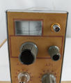
The Tektronix 1405 TV Sideband Adapter is a signal generator used with a spectrum analyzer such as the 7L12 or 7L13 to analyze the sideband response of a television transmitter or other video circuitry.
The 1405 generates a composite video signal, the picture portion of which is a constant-amplitude sine wave signal that sweeps from 15-0-15 MHz. This signal is used to modulate the TV transmitter. The sideband response of the transmitter will be displayed on the spectrum analyzer.
Links
Documents Referencing 1405
| Document | Class | Title | Authors | Year | Links |
|---|---|---|---|---|---|
| TekWeek (partial) October 10, 1975.pdf | Article | Spectrum analyzers require high technology | Thor Hallen • Dave Friedley | 1975 | Spectrum Analyzers • Pentrix • 7L5 • 5L4 • 7L12 • 7L13 • 1401 • 491 • 1405 • 1502 • 1503 |
| Tekscope 1976 V8 N2.pdf | Article | New Products | 1976 | 670A • 1405 • 1410 • 1470 • 1474 • AM511 • 1480 |
Pictures
The prototype of the 1405 was a 7000-series plug-in.


