P6202: Difference between revisions
No edit summary |
mNo edit summary |
||
| (30 intermediate revisions by 4 users not shown) | |||
| Line 1: | Line 1: | ||
* [ | {{Probe Sidebar | ||
|manufacturer=Tektronix | |||
|model=P6202 | |||
|summary=500 MHz Active FET Probe | |||
|image=Tek-p6202-in-case.jpg | |||
|caption=Tektronix P6202 | |||
|for=50 Ω scope inputs | |||
|introduced=1976 | |||
|discontinued=2000 | |||
|manuals= | |||
* [[Media:070-2067-00.pdf|Tektronix P6202 Manual]] | |||
* [[Media:070-3642-02.pdf|Tektronix P6202A Manual]] | |||
}} | |||
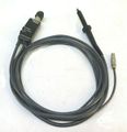
The '''Tektronix P6202''' is a 500 MHz active 10× FET probe with 50 Ω output impedance, introduced in 1976. | |||
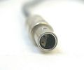
The P6202 has its own mains power supply, the [[P6202A]] (1980) has a [[LEMO S-series connector]] fitting the [[7000-series scopes]]' probe power outlets. | |||
{{BeginSpecs}} | |||
{{Spec | Bandwidth | DC to 500 MHz (16 Hz lower limit with additional AC coupling tip) }} | |||
{{Spec | Rise time | < 0.7 ns }} | |||
{{Spec | Attenuation | 10 : 1 (100 : 1 with additional 10× attenuator tip, 010-0384-00) }} | |||
{{Spec | Input impedance | 10 MΩ // 2 pF with or without additional 10× attenuator tip, +2 pF for AC coupling tip }} | |||
{{Spec | Input range | ± 6 V (± 60 V with additional 10× attenuator tip) }} | |||
{{Spec | DC offset | ± 55 V (± 200 V with additional 10× attenuator tip) }} | |||
{{Spec | Max input | ± 200 V (nondestructive) }} | |||
{{Spec | Cable length | 2 m (6.5') }} | |||
{{EndSpecs}} | |||
==Links== | |||
{{Documents|Link=P6202}} | |||
{{Documents|Link=P6202A}} | |||
{{PatentLinks|P6202}} | |||
{{PatentLinks|P6202A}} | |||
==Internals== | |||
An initial 8 MΩ : 2 MΩ divider drives a dual JFET (source follower + current source), a PNP emitter follower and finally an NPN emitter follower as a cable driver. | |||
These stages use SMD components located in the probe tip. | |||
The probe control box at the end of the coax only contains a ±7 V regulator, a switchable 50 Ω terminator, and the offset potentiometers that supply ±15 V to the bottom of the input divider. | |||
There is no input protection apart from the divider. | |||
==Compatible probe tip to coaxial adapters== | |||
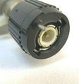
While the probe body is wider than regular [[miniature modular probe]]s, some accessories are compatible. The manual lists the following adapters in particular: | |||
* [[017-0076-00]] GR | |||
* [[017-0088-00]] GR with internal 50 Ω Termination | |||
* [[031-0084-01]] BNC | |||
==Pictures== | |||
===P6202=== | |||
<gallery> | |||
Tek-p6202-case-open.jpg | Carrying case | |||
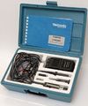
Tek-p6202-in-case.jpg | Probe in case, with power supply, 10:1 pre-divider tip (010-0384-00), hook tip, AC coupling tip and connection box. | |||
Tek-p6202-tip-1.jpg | Amplifier in probe tip (SMD components in 1976!) | |||
Tek-p6202-tip-2.jpg | Amplifier in probe tip, reverse | |||
Tek-p6202-box1.jpg | Connection box | |||
Tek-p6202-box2.jpg | |||
Tek-p6202-box3.jpg | |||
Tek-p6202-box4.jpg | |||
P6202-circuit.jpg | Schematic | |||
</gallery> | |||
===P6202A=== | |||
<gallery> | |||
Tek_P6202A_1.jpg | |||
Tek_P6202A_2.jpg | |||
Tek_P6202A_3.jpg | |||
Tek_P6202A_4.jpg | |||
Tek_P6202A_5.jpg | |||
Tek_P6202A_6.jpg | Probe power connector | |||
Tek-p6202-case.jpg | Case exterior | |||
</gallery> | |||
===Measurements=== | |||
Rise time of a [[P6202]] 500 MHz FET probe measured on a [[7S12]] plugin in a [[7844]] mainframe (with 25 ps [[S-52]] pulse generator head and 25 ps [[S-4]] sampling head). | |||
Measured rise time ~440 ps observed on this specimen is equivalent to 795 MHz bandwidth. | |||
<gallery> | |||
P6202-risetime-7s12-1ns.jpg | at 1 ns/Div | |||
P6202-risetime-7s12-100ps.jpg | at 100 ps/Div | |||
</gallery> | |||
==Components== | |||
{{Parts|P6202}} | |||
{{Parts|P6202A}} | |||
[[Category:Active oscilloscope probes]] | |||
Latest revision as of 04:39, 29 October 2024
The Tektronix P6202 is a 500 MHz active 10× FET probe with 50 Ω output impedance, introduced in 1976.
The P6202 has its own mains power supply, the P6202A (1980) has a LEMO S-series connector fitting the 7000-series scopes' probe power outlets.
Key Specifications
| Bandwidth | DC to 500 MHz (16 Hz lower limit with additional AC coupling tip) |
|---|---|
| Rise time | < 0.7 ns |
| Attenuation | 10 : 1 (100 : 1 with additional 10× attenuator tip, 010-0384-00) |
| Input impedance | 10 MΩ // 2 pF with or without additional 10× attenuator tip, +2 pF for AC coupling tip |
| Input range | ± 6 V (± 60 V with additional 10× attenuator tip) |
| DC offset | ± 55 V (± 200 V with additional 10× attenuator tip) |
| Max input | ± 200 V (nondestructive) |
| Cable length | 2 m (6.5') |
Links
Documents Referencing P6202
| Document | Class | Title | Authors | Year | Links |
|---|---|---|---|---|---|
| Tekscope 1976 V8 N2.pdf | Article | A New Low-cost 500 MHz Probe | Ron Lang | 1976 | P6202 |
Documents Referencing P6202A
- (no results)
Internals
An initial 8 MΩ : 2 MΩ divider drives a dual JFET (source follower + current source), a PNP emitter follower and finally an NPN emitter follower as a cable driver. These stages use SMD components located in the probe tip. The probe control box at the end of the coax only contains a ±7 V regulator, a switchable 50 Ω terminator, and the offset potentiometers that supply ±15 V to the bottom of the input divider. There is no input protection apart from the divider.
Compatible probe tip to coaxial adapters
While the probe body is wider than regular miniature modular probes, some accessories are compatible. The manual lists the following adapters in particular:
- 017-0076-00 GR
- 017-0088-00 GR with internal 50 Ω Termination
- 031-0084-01 BNC
Pictures
P6202
-
Carrying case
-
Probe in case, with power supply, 10:1 pre-divider tip (010-0384-00), hook tip, AC coupling tip and connection box.
-
Amplifier in probe tip (SMD components in 1976!)
-
Amplifier in probe tip, reverse
-
Connection box
-
-
-
-
Schematic
P6202A
-
-
-
-
-
-
Probe power connector
-
Case exterior
Measurements
Rise time of a P6202 500 MHz FET probe measured on a 7S12 plugin in a 7844 mainframe (with 25 ps S-52 pulse generator head and 25 ps S-4 sampling head). Measured rise time ~440 ps observed on this specimen is equivalent to 795 MHz bandwidth.
-
at 1 ns/Div
-
at 100 ps/Div
Components
Some Parts Used in the P6202
| Part | Part Number(s) | Class | Description | Used in |
|---|---|---|---|---|
| 151-1100-01 | 151-1100-01 | Discrete component | dual JFET transistor | P6202 • P6202A |
Some Parts Used in the P6202A
| Part | Part Number(s) | Class | Description | Used in |
|---|---|---|---|---|
| 151-1100-01 | 151-1100-01 | Discrete component | dual JFET transistor | P6202 • P6202A |


