P6135: Difference between revisions
Jump to navigation
Jump to search
No edit summary |
(please don't leave the name of the specification empty, the Spec template populates a database table) |
||
| (10 intermediate revisions by 3 users not shown) | |||
| Line 1: | Line 1: | ||
{{Probe Sidebar | {{Probe Sidebar | ||
|manufacturer=Tektronix | |manufacturer=Tektronix | ||
|model= | |model=P6135 | ||
|summary= | |summary=150 MHz, ×10 differential probe pair | ||
|image=Tek p6135 1.jpg | |image=Tek p6135 1.jpg | ||
|caption=Tektronix | |caption=Tektronix P6135 (one of a pair) | ||
|for=1 MΩ scope inputs | |for=1 MΩ scope inputs | ||
|series= | |series= | ||
| Line 12: | Line 12: | ||
* [[Media:070-7675-02.pdf|Tektronix P6135A Manual]] | * [[Media:070-7675-02.pdf|Tektronix P6135A Manual]] | ||
}} | }} | ||
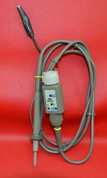
The '''Tektronix | The '''Tektronix P6135(A)''' is a differential probe pair matched to minimize differences in impedance and signal delay, | ||
to maintain CMRR up to 20,000:1 when used with differential amplifiers such as the [[7A13]], [[7A22]] or [[11A33]]. | to maintain CMRR up to 20,000:1 when used with differential amplifiers such as the [[7A13]], [[7A22]] or [[11A33]]. | ||
Note that unlike most x10 probes, the P6135 and P6135A have an input resistance of 1 MΩ rather than 10 MΩ. | |||
The P6135 is a [[Subminiature modular probes|subminiature modular probe]] with a limited compensation range around 15 pF. | |||
The P6135A is a larger [[compact modular probes|compact modular probe]] and comes with three different tips for increased compensation range, matching the [[11A33]] − red, [[7A13]] − black, and [[7A22]] − blue. | |||
The P6135A model can therefore be seen as a replacement of the [[P6055]]. | |||
{{BeginSpecs}} | {{BeginSpecs}} | ||
{{Spec | | {{Spec | Bandwidth | 150 MHz on [[11A33]], 90 MHz on [[7A13]] }} | ||
{{Spec | Max. Input | ±500 V (DC + peak AC) derated above 1.3 MHz }} | |||
{{Spec | Attenuation | Adjustable to ×10 }} | {{Spec | Attenuation | Adjustable to ×10 }} | ||
{{Spec | CMRR | 10,000:1 on [[11A33]], 20,000:1 on [[7A13]] | {{Spec | Compensation Range | | ||
* P6135: 1 MΩ // 13-17 pF | |||
* P6135A, red tip: 1 MΩ // 13-17 pF | |||
* P6135A, black tip: 1 MΩ // 18-22 pF | |||
* P6135A, blue tip: 1 MΩ // 45-49 pF | |||
}} | |||
{{Spec | Input Impedance | | |||
* P6135: ''Please Add'' | |||
* P6135A, red tip: 1 MΩ // 10.5 ± 0.6 pF | |||
* P6135A, black tip: 1 MΩ // 11.0 ± 0.6 pF | |||
* P6135A, blue tip: 1 MΩ // 13.7 ± 0.6 pF | |||
}} | |||
{{Spec | CMRR | 10,000:1 on [[11A33]], 20,000:1 on [[7A13]] }} | |||
{{EndSpecs}} | {{EndSpecs}} | ||
==Pictures== | ==Pictures== | ||
===P6135=== | |||
<gallery> | <gallery> | ||
Tek p6135 1.jpg | Tek p6135 1.jpg | ||
| Line 28: | Line 46: | ||
Tek p6135 3.jpg | Tek p6135 3.jpg | ||
Tek p6135 4.jpg | Tek p6135 4.jpg | ||
</gallery> | |||
===P6135A=== | |||
<gallery> | |||
P6135A_1.jpg | |||
</gallery> | </gallery> | ||
[[Category:1 MΩ Oscilloscope probes]] | [[Category:1 MΩ Oscilloscope probes]] | ||
[[Category:Passive Differential probes]] | [[Category:Passive Differential probes]] | ||
[[Category:Subminiature modular probes]] | |||
Latest revision as of 08:36, 24 August 2024
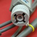
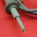
The Tektronix P6135(A) is a differential probe pair matched to minimize differences in impedance and signal delay, to maintain CMRR up to 20,000:1 when used with differential amplifiers such as the 7A13, 7A22 or 11A33. Note that unlike most x10 probes, the P6135 and P6135A have an input resistance of 1 MΩ rather than 10 MΩ.
The P6135 is a subminiature modular probe with a limited compensation range around 15 pF. The P6135A is a larger compact modular probe and comes with three different tips for increased compensation range, matching the 11A33 − red, 7A13 − black, and 7A22 − blue. The P6135A model can therefore be seen as a replacement of the P6055.
Key Specifications
| Bandwidth | 150 MHz on 11A33, 90 MHz on 7A13 |
|---|---|
| Max. Input | ±500 V (DC + peak AC) derated above 1.3 MHz |
| Attenuation | Adjustable to ×10 |
| Compensation Range |
|
| Input Impedance |
|
| CMRR | 10,000:1 on 11A33, 20,000:1 on 7A13 |


