UPIK 40: Difference between revisions
mNo edit summary |
mNo edit summary |
||
| Line 2: | Line 2: | ||
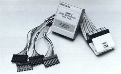
The '''UPIK40''' is a harness that enables easy connection to a DIP-40 integrated circuit package. It is meant to be used with the [[1240]] and [[1241]] alongside disassembly software. | The '''UPIK40''' is a harness that enables easy connection to a DIP-40 integrated circuit package. It is meant to be used with the [[1240]] and [[1241]] alongside disassembly software. | ||
The pictures below were taken of a Z80 probe interface. The pin-out for the 40 pin female connector that connects the ribbon cable (aka octopus cable as seen in photo 6) adapter to the probes follows. NOTE: The connector numbering follows the DIP pin numbering convention (down one side and up the other), NOT the regular ribbon cable standard of odds down one side, evens on the other. Each 40-pin microprocessor gets its own version of the octopus. | |||
{| class="wikitable" | | |||
{| class="wikitable" | |||
|- | |- | ||
! Pin | ! Pin | ||
! Color | ! Color | ||
! Primary | ! Primary<br />91A24 Pod | ||
91A24 Pod | |||
! 1240 Pod | ! 1240 Pod | ||
! Pod color | ! Pod color | ||
! Secondary | ! Secondary<br />91A24 Pod | ||
91A24 Pod | |||
! 1240 Pod | ! 1240 Pod | ||
! Pod Color | ! Pod Color | ||
| Line 395: | Line 386: | ||
| | | | ||
|- | |- | ||
} | |} | ||
A spreadsheet version of this which also contains the 6502 connections from the PDF, and extrapolated 6800 pin outs (with maybe the right connections for control signals) is here: | |||
* [[Media:Z80.tar|Z80 pinout]] | |||
* [[Media:12RM63_(6502-C02)_Signal_Map.PDF|6502 signal map]] | |||
== Pictures == | == Pictures == | ||
Latest revision as of 04:29, 4 December 2022

The UPIK40 is a harness that enables easy connection to a DIP-40 integrated circuit package. It is meant to be used with the 1240 and 1241 alongside disassembly software.
The pictures below were taken of a Z80 probe interface. The pin-out for the 40 pin female connector that connects the ribbon cable (aka octopus cable as seen in photo 6) adapter to the probes follows. NOTE: The connector numbering follows the DIP pin numbering convention (down one side and up the other), NOT the regular ribbon cable standard of odds down one side, evens on the other. Each 40-pin microprocessor gets its own version of the octopus.
| Pin | Color | Primary 91A24 Pod |
1240 Pod | Pod color | Secondary 91A24 Pod |
1240 Pod | Pod Color |
|---|---|---|---|---|---|---|---|
| 1 | orange | 2a | 3 | orange | |||
| 2 | yellow | 2a | 3 | yellow | |||
| 3 | green | 2a | 3 | green | |||
| 4 | blue | 2a | 3 | blue | |||
| 5 | violet | 2a | 3 | violet | |||
| 6 | N/C | ||||||
| 7 | yellow | 1B | 1 | yellow | |||
| 8 | orange | 1B | 1 | orange | |||
| 9 | green | 1B | 1 | green | |||
| 10 | blue | 1B | 1 | blue | |||
| 11 | N/C | ||||||
| 12 | red | 1B | 1 | red | |||
| 13 | violet | 1B | 1 | violet | |||
| 14 | black | 1B | 1 | black | |||
| 15 | brown | 1B | 1 | brown | |||
| 16 | yellow | 1C | 2 | yellow | |||
| 17 | N/C | ||||||
| 18 | violet | 1C | 2 | violet | |||
| 19 | black | 2A | 3 | white | 1C | 2 | orange |
| 20 | black | 1A | 0 | white | 1C | 2 | green |
| 21 | black | 1C | 2 | red | 1C | 2 | white |
| 22 | black | 1C | 2 | brown | 1B | 1 | white |
| 23 | blue | 1C | 2 | blue | |||
| 24 | N/C | ||||||
| 25 | N/C | ||||||
| 26 | N/C | ||||||
| 27 | black | 1C | 2 | black | |||
| 28 | N/C | ||||||
| 29 | black | Ground Lug | |||||
| 30 | black | 1A | 0 | black | |||
| 31 | brown | 1A | 30 | brown | |||
| 32 | red | 1A | 0 | red | |||
| 33 | orange | 1A | 0 | orange | |||
| 34 | yellow | 1A | 0 | yellow | |||
| 35 | green | 1A | 0 | green | |||
| 36 | blue | 1A | 0 | blue | |||
| 37 | violet | 1A | 0 | violet | |||
| 38 | black | 2A | 3 | black | |||
| 39 | brown | 2A | 3 | brown | |||
| 40 | red | 2A | 3 | red |
A spreadsheet version of this which also contains the 6502 connections from the PDF, and extrapolated 6800 pin outs (with maybe the right connections for control signals) is here:


