P7001: Difference between revisions
No edit summary |
No edit summary |
||
| Line 1: | Line 1: | ||
The Tektronix P7001 is a digitizer, processor, | The '''Tektronix P7001''' is a digitizer, processor, and memory for the [[7704A]] oscilloscope. | ||
and memory for the [[7704A]] oscilloscope. | |||
The design of the P7001 assumes | The design of the P7001 assumes it will be part of a 7704A system, and that the 7704A will be displaying a steady trace. | ||
it will be part of a 7704A system, | The vertical and horizonal plug-ins control the beam as they would in any 7000-series scope. | ||
and that the 7704A will be | The P7001 periodically samples the horizontal and vertical signals simultaneously as they pass from the plug-ins | ||
displaying a steady trace. | |||
The vertical and horizonal plug-ins | |||
control the beam as they would | |||
in any 7000-series scope. | |||
The P7001 periodically samples | |||
the horizontal and vertical signals simultaneously | |||
as they pass from the plug-ins | |||
to the vertical and horizontal amplifiers. | to the vertical and horizontal amplifiers. | ||
This allows it to fill the memory with data points | This allows it to fill the memory with data points represented as coordinate pairs, (x1,y1), (x2,y2), (x3,y3), etc. | ||
represented as coordinate pairs, (x1,y1), (x2,y2), (x3,y3), etc. | |||
It is not necessary that x2 be greater than x1. | It is not necessary that x2 be greater than x1. | ||
The samples can be taken out-of-order | The samples can be taken out-of-order with respect to their equivalent time in the waveform. | ||
with respect to their equivalent time in the waveform. | |||
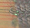
The signal coming from the acquisition unit enters | The signal coming from the acquisition unit enters a fast [[sampling diodes|four-diode]] sample and hold circuit | ||
a fast [[sampling diodes|four-diode]] sample and hold circuit | |||
where it is sampled at 150Ksamp/sec. | where it is sampled at 150Ksamp/sec. | ||
Each sample is digitized using a successive-approximation scheme. | Each sample is digitized using a successive-approximation scheme. | ||
The analog to digital converter is made of several chips: | The analog to digital converter is made of several chips: | ||
a digital to analog converter, a comparator, and control logic. | a digital to analog converter, a comparator, and control logic. | ||
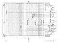
The Acquisition Unit of the 7704A, | The P7001 has its own power supply built into it, independent of the power supply in the acquisition unit of the 7704A. | ||
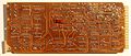
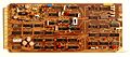
the P7001 Processor, | It has a backplane with an asynchronous bus and several cards that plug into that bus: | ||
and the Display Unit of the 7704A | sampler, analog to digital converter, memory, external digital interface, and display electronics. | ||
are connected by the | Early versions of the P7001 use core memory, later versions use semiconductor RAM. The bus is used for low speed signals. | ||
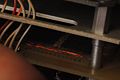
Acquisition-Processor-Display (APD) Interface | High speed signals are sent through coaxial cables that connect to the cards using Peltola connectors. | ||
shown below. | |||
The Acquisition Unit of the 7704A, the P7001 Processor, and the Display Unit of the 7704A are connected by the | |||
Acquisition-Processor-Display (APD) Interface shown below. | |||
[http://w140.com/p7001 Tektronix P7001 Manuals (PDF)] | [http://w140.com/p7001 Tektronix P7001 Manuals (PDF)] | ||
| Line 48: | Line 28: | ||
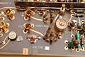
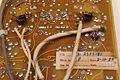
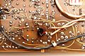
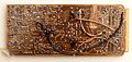
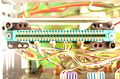
== Sample and Hold Card == | == Sample and Hold Card == | ||
<gallery> | <gallery> | ||
P7001 vert sample bridge.jpg|Vertical sampling bridge | |||
P7001 horiz sample bridge.jpg|Horizontal sampling bridge | |||
P7001 strobe gen.jpg|Sampling strobe generator | |||
P7001 sample hold card conn.jpg|Sample and hold edge connector | |||
P7001 sample hold back transformers.jpg|Sample and hold transformers | |||
P7001 sample hold back trans.jpg|Sample and hold transformer | |||
P7001 sample hold back.jpg|Sample and hold rear | |||
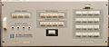
P7001 front.jpg|Front panel | |||
P7001 top.jpg|Top view | |||
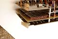
P7001 bus front.jpg|Front of backplane | |||
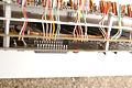
P7001 bus back.jpg|Rear of backplane | |||
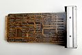
P7001 connector3.jpg|Interunit connector | |||
P7001 connector2.jpg|Interunit connector | |||
P7001 connector1.jpg|Interunit connector | |||
P7001 dpo controller.jpg|Controller card | |||
P7001 dpo controller board.jpg|Controller card | |||
P7001 dpo controller back.jpg|Controller card | |||
P7001 diode decoder.jpg|Address decoder | |||
P7001 core boards.jpg|Core boards | |||
Core mat.jpg|Core memory | |||
Core20.jpg|Core closeup | |||
Core17.jpg|Core closeup | |||
P7001 ps.jpg|Switching power supply | |||
P7001 z-axis front panel rear.jpg|Z-axis and panel controller | |||
P7001 z-axis front panel.jpg|Z-axis and panel controller | |||
P7001 readout interface.jpg|Readout interface | |||
P7001 front panel connections.jpg|Front panel connections | |||
P7001 display generator rear.jpg|Display generator rear | |||
P7001 display generator.jpg|Display generator | |||
P7001 adc rear.jpg|ADC rear | |||
P7001 adc probe points.jpg|Probe points on ADC | |||
P7001 adc.jpg|ADC | |||
P7001 ps1.jpg|Power supply schematic 1 | |||
P7001 ps2.jpg|Power supply schematic 2 | |||
P7001 apd interconnect.jpg|APD Interconnect | |||
</gallery> | </gallery> | ||
Revision as of 12:34, 3 June 2017
The Tektronix P7001 is a digitizer, processor, and memory for the 7704A oscilloscope.
The design of the P7001 assumes it will be part of a 7704A system, and that the 7704A will be displaying a steady trace. The vertical and horizonal plug-ins control the beam as they would in any 7000-series scope. The P7001 periodically samples the horizontal and vertical signals simultaneously as they pass from the plug-ins to the vertical and horizontal amplifiers. This allows it to fill the memory with data points represented as coordinate pairs, (x1,y1), (x2,y2), (x3,y3), etc. It is not necessary that x2 be greater than x1. The samples can be taken out-of-order with respect to their equivalent time in the waveform.
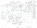
The signal coming from the acquisition unit enters a fast four-diode sample and hold circuit where it is sampled at 150Ksamp/sec. Each sample is digitized using a successive-approximation scheme. The analog to digital converter is made of several chips: a digital to analog converter, a comparator, and control logic.
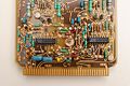
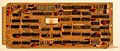
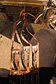
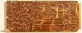
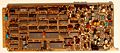
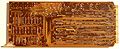
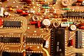
The P7001 has its own power supply built into it, independent of the power supply in the acquisition unit of the 7704A. It has a backplane with an asynchronous bus and several cards that plug into that bus: sampler, analog to digital converter, memory, external digital interface, and display electronics. Early versions of the P7001 use core memory, later versions use semiconductor RAM. The bus is used for low speed signals. High speed signals are sent through coaxial cables that connect to the cards using Peltola connectors.
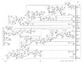
The Acquisition Unit of the 7704A, the P7001 Processor, and the Display Unit of the 7704A are connected by the Acquisition-Processor-Display (APD) Interface shown below.
Sample and Hold Card
-
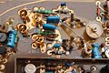
Vertical sampling bridge
-
Horizontal sampling bridge
-
Sampling strobe generator
-
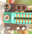
Sample and hold edge connector
-
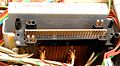
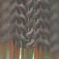
Sample and hold transformers
-
Sample and hold transformer
-
Sample and hold rear
-
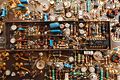
Front panel
-
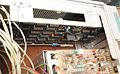
Top view
-
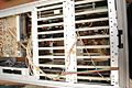
Front of backplane
-
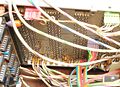
Rear of backplane
-
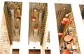
Interunit connector
-
Interunit connector
-
Interunit connector
-
Controller card
-
Controller card
-
Controller card
-
Address decoder
-
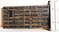
Core boards
-
Core memory
-
Core closeup
-
Core closeup
-

Switching power supply
-
Z-axis and panel controller
-
Z-axis and panel controller
-
Readout interface
-
Front panel connections
-
Display generator rear
-
Display generator
-
ADC rear
-
Probe points on ADC
-

ADC
-
Power supply schematic 1
-
Power supply schematic 2
-
APD Interconnect


