515: Difference between revisions
mNo edit summary |
No edit summary |
||
| Line 1: | Line 1: | ||
{{Oscilloscope Sidebar |manufacturer=Tektronix | | {{Oscilloscope Sidebar | ||
|manufacturer=Tektronix | |||
model= 515| | |series= | ||
summary=15 MHz Tube scope | | |model=515 | ||
image=515a trace.jpg | | |summary=15 MHz Tube scope | ||
caption=Tektronix 515 front | | |image=515a trace.jpg | ||
introduced=1955 | | |caption=Tektronix 515 front | ||
discontinued=(?) | | |introduced=1955 | ||
manuals= | |discontinued=(?) | ||
* [[Media:070-247.pdf|Tektronix 515 Manual]] ( | |manuals= | ||
* [[Media:070-247.pdf|Tektronix 515 Manual]] (OCR)<br /><small>Alternate: [[Media:TekInstructionManual_515_515A_P31.tif|515/515A (P31)]] (29M TIF) </small> | |||
<small> | <small> | ||
* 515A Factory Calibration Procedure: [[Media:tek_515a_fcp.pdf|May 1960]] ( | * 515A Factory Calibration Procedure: [[Media:tek_515a_fcp.pdf|May 1960]] (OCR) / [[Media:Tek 515a fcp dec 1968.pdf | December 1968]] (needs OCR) | ||
* [[Media:Tek 515a mod 760a.pdf|Tektronix 515A Mod 760A]] | * [[Media:Tek 515a mod 760a.pdf|Tektronix 515A Mod 760A]] | ||
</small> | </small> | ||
Revision as of 04:28, 2 November 2022
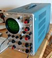
The Tektronix 515 is a 15 MHz single-trace all-tube oscilloscope introduced in 1955. It does not use plug-ins.
A rack-mount version, the RM15 was also sold. There is also a 515A (serial numbers 101 through 1000 are "Type 515", 1001 and upward are "Type 515A").
The 515A has a Z-axis input and slightly higher vertical sensitivity than the 515. Maximum vertical sensitivity is 100 mV/Div for the 515 and 50 mV/Div for the 515A. The 516 is essentially a dual-trace version of the 515.
The 515 and 515A are fan-cooled, both in benchtop and rackmount forms.
Key Specifications
| Channels | One vertical channel (two input connectors and a switch to select) |
|---|---|
| Bandwidth | DC to 15 MHz |
| Rise time | 23 ns |
| Deflection | 50 mV/div to 20 V/div (515A), 100 mV/div to 50 V/div (515) |
| Sweep | 0.2 μs/div to 2 s/div |
| CRT | T55 CRT CRT, P31 phosphor standard, 6 cm linear vertical deflection |
| Input impedance | 1 MΩ // 30 pF |
| Power consumption | 275 W |
| Weight | 40 pounds (18 kg) |
Links
- Tek 515A @ museum-nt.de
- Tektronix 515A checkout @ youtube.com
Internals
The HV power supply uses three 5642 rectifiers to produce +2,325 V for the CRT anode and −1,675 V for the CRT cathode. The LV power supply is linear, using a 6080 tube as the pass tube of the series regulator for +300 V and +100 V supply. The −150 V supply is regulated by a 6AU5 tube. The voltage reference for the −150 V supply is a 5651 tube.
The 515 and 515A use selenium rectifiers. A kit was later made availa blefor converting them to silicon rectifiers for improved reliability. Starting at serial number 4424, the 515A used the 120-142 power transformer, the same part that is used in the 516.
The vertical amplifier is fully differential, DC-coupled, and all tube. The stages are as follows:
- input buffer, cathode followers, 6AU6
- first gain stage, differential amplifier, T-coil, 12BY7
- unity gain buffer, cathode follower, 6DJ8
- output amplifier, differential amplifier, T-coil, 6CL6
The horizontal amplifier uses half of a 6DJ8 as a buffer, followed by a 6DJ8 as a differential amplifier and phase splitter, followed by the two halves of another 6DJ8 as the output cathode followers driving the horizontal CRT deflection plates.
The trigger is a 6DJ8 differential trigger amplifier followed by a 6DJ8 Schmitt trigger.
Pictures
-
RM15 front view
-
RM15 side view
-
Vertical signal path
-
RM15 top view
-
RM15 bottom view
-
515A
-
515A
-
515A
-
515A Left internal view
-
515A CRT circuit
-
515A HV power supply
-
515A HV power supply
-
515A HV power supply
-
-
515A
-
515A left internal
-
515A right internal
-
515A S1
-
515A S1
-
515A S1
-
515A S1
-
515A S1
-
RM15
-
RM15
-
RM15
-
RM15
-
RM15 rear
-
515A
-
515A
-
Blue 515A


