TR502: Difference between revisions
Jump to navigation
Jump to search
No edit summary |
No edit summary |
||
| Line 4: | Line 4: | ||
* [http://w140.com/smb/TR502_SM.pdf Tektronix TR502 Manual (OCR, PDF)] | * [http://w140.com/smb/TR502_SM.pdf Tektronix TR502 Manual (OCR, PDF)] | ||
}} | }} | ||
The TR502 is intended to work with the [[7L13]] spectrum analyzer | The TR502 is intended to work with the [[7L13]] and [[7L14]] spectrum analyzer plugins from the 7000 series. It also works with a [[7L12]]. | ||
The [[TR501]] and TR502 are essentially the same instrument with the exception of the output attenuators and logic interface in the TR502, which adds dot marker support for the 7L13 via the TRACK GEN LOGIC connector. A 012-0648-00 cable with [[LEMO_S-series_connector|6-pin LEMO Connectors]] is required for this functionality. | The [[TR501]] and TR502 are essentially the same instrument with the exception of the output attenuators and logic interface in the TR502, which adds dot marker support for the 7L13 via the TRACK GEN LOGIC connector. A 012-0648-00 cable with [[LEMO_S-series_connector|6-pin LEMO Connectors]] is required for this functionality. | ||
Revision as of 14:51, 27 October 2021
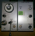
The Tektronix TR502 is a 1.8 GHz tracking generator plug-in for the TM500 system.
The TR502 is intended to work with the 7L13 and 7L14 spectrum analyzer plugins from the 7000 series. It also works with a 7L12.
The TR501 and TR502 are essentially the same instrument with the exception of the output attenuators and logic interface in the TR502, which adds dot marker support for the 7L13 via the TRACK GEN LOGIC connector. A 012-0648-00 cable with 6-pin LEMO Connectors is required for this functionality. The TR503 is similar but has different oscillator and intermediate frequencies (see link).
Key Specifications
- please add
Links
- Tektronix TR502 @ barrytech.com
- Tektronix TR502 @ radiomuseum.org
- TekScope Vol. 7 No. 5, 1975 p.11+: Fred Telewski, A high-stability 100 kHz to 1.8 GHz tracking generator
- Converting a TR502 to a TR503 configuration
Pictures
-
-
-
-
-
TR501/TR502 block diagram


