Delay line: Difference between revisions
No edit summary |
No edit summary |
||
| Line 21: | Line 21: | ||
* Delay between amplifier and CRT: [[516]], [[533]], [[545]], [[551]], [[555]] | * Delay between amplifier and CRT: [[516]], [[533]], [[545]], [[551]], [[555]] | ||
=Types of Delays= | |||
There are five main ways delay lines are implemented | There are five main ways delay lines are implemented | ||
in Tektronix scopes | in Tektronix scopes | ||
==Conventional coaxial cable== | |||
Used in [[517]], [[4S1]], [[3S76]], and [[1S1]]. | |||
<gallery> | |||
File:Tek_3s76_left.jpg|Coaxial cable delay line in a 3S76 | |||
</gallery> | |||
==Semi-rigid air-core coax== | |||
Used in [[519]], [[113]] | |||
<gallery> | |||
File:Timkoeth_519_TWK_6537.jpg|Delay line in a 519. | |||
</gallery> | |||
==Unshielded helically wound differential transmission line== | |||
Used in [[581]], [[585]] | |||
<gallery> | |||
File:585a_delay1.jpg|Section of a [[585|585A]] delay line. Two conductors are wound around a plastic core, one conductor clockwise, the other counterclockwise. | |||
</gallery> | |||
==Helically wound differential transmission line inside braided shield== | |||
Used in [[545|545B]], [[547]] | |||
<gallery> | |||
File:Tek rm545b delay.jpg|Section of a [[545|RM545B]] Delay Line. From outside to inside: Outer Braid, Plastic, Conductors, Plastic Core | |||
</gallery> | |||
==Lumped L-C== | |||
Lumped L-C delay lines are used in the [[511|511AD]], [[513|513D]], [[514|514D]], [[541]], [[545]], [[551]], [[555]], and [[524]]. | |||
These delay lines must be carefully adjusted for best pulse response. | |||
A typical lumped L-C delay line has about 30 sections, and each section typically | A typical lumped L-C delay line has about 30 sections, and each section typically | ||
has an adjustable capacitor. In some applications, lumped L-C delay lines | has an adjustable capacitor. In some applications, lumped L-C delay lines | ||
| Line 36: | Line 53: | ||
most coaxial cables are 125 ohms or less. | most coaxial cables are 125 ohms or less. | ||
<gallery> | |||
File:Tek_514d_delay_trimmers.jpg|Delay line trimmer capacitors in a 514D. | |||
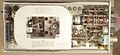
File:551_leftint.jpg|Delay line in a 551 wraps around the rear left side of the scope. | |||
</gallery> | |||
=Delay Lines in Sampling Oscilloscopes= | |||
The purpose of delay lines in sampling scopes is | The purpose of delay lines in sampling scopes is | ||
the same as for conventional non-sampling scopes. | the same as for conventional non-sampling scopes. | ||
| Line 48: | Line 72: | ||
is to use [[random sampling]]. | is to use [[random sampling]]. | ||
=See Also= | |||
* http://www.freepatentsonline.com/2756394.pdf | * http://www.freepatentsonline.com/2756394.pdf | ||
* http://www.physics.usyd.edu.au/ugrad/sphys/expt/Expt_6.pdf | * http://www.physics.usyd.edu.au/ugrad/sphys/expt/Expt_6.pdf | ||
| Line 55: | Line 80: | ||
* http://w140.com/electronics_letters_apr_1970.pdf | * http://w140.com/electronics_letters_apr_1970.pdf | ||
* http://w140.com/wigington_nahman.pdf | * http://w140.com/wigington_nahman.pdf | ||
[[Category:Electromechanical components]] | [[Category:Electromechanical components]] | ||
Revision as of 12:00, 12 September 2015
The purpose of delay lines in oscilloscopes is to allow observation of the leading edge of the trigger event. In the vertical signal path, before the delay line, there is typically a trigger pick-off which supplies an undelayed copy of the vertical signal to the the trigger and sweep circuitry. Trigger and sweep circuitry need about 60ns to react when presented with the trigger event. Without a delay line, the trigger event would already have come and gone before the scope can trigger and sweep. By sending the input signal through a delay line, the scope will have triggered and begun sweeping by the time the trigger event emerges from the delay line. Thus, the trigger event is drawn on the screen where the operator can see it, photograph it, or record it by other means.
The first Tektronix scope to contain a delay line was the 513D, which uses an L-C network. Soon after, the 517 appeared, using 51 feet of RG-63U coaxial cable as a 65 nanosecond delay line. 7000-series scopes use special twin-lead delay cables. The delay line in the 519 is a large coil of low-loss air-dielectric semi-rigid coax.
The location of the delay line in the instrument block diagram varies:
- Delay before any active electronics: 4S1, 1S1
- Delay between amplifiers: 517, 7000 series scopes, 315, 547, 524
- Delay between amplifier and CRT: 516, 533, 545, 551, 555
Types of Delays
There are five main ways delay lines are implemented in Tektronix scopes
Conventional coaxial cable
Used in 517, 4S1, 3S76, and 1S1.
-
Coaxial cable delay line in a 3S76

Semi-rigid air-core coax
-
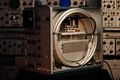
Delay line in a 519.

Unshielded helically wound differential transmission line
-
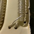
Section of a 585A delay line. Two conductors are wound around a plastic core, one conductor clockwise, the other counterclockwise.

Helically wound differential transmission line inside braided shield
-
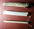
Section of a RM545B Delay Line. From outside to inside: Outer Braid, Plastic, Conductors, Plastic Core

Lumped L-C
Lumped L-C delay lines are used in the 511AD, 513D, 514D, 541, 545, 551, 555, and 524. These delay lines must be carefully adjusted for best pulse response. A typical lumped L-C delay line has about 30 sections, and each section typically has an adjustable capacitor. In some applications, lumped L-C delay lines were preferred over distributed delays (e.g., coax) because of impedance. It is possible for a lumped L-C delay line to have a characteristic impedance of 1000 ohms, while most coaxial cables are 125 ohms or less.
-
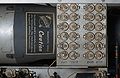
Delay line trimmer capacitors in a 514D.
-
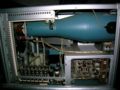
Delay line in a 551 wraps around the rear left side of the scope.


Delay Lines in Sampling Oscilloscopes
The purpose of delay lines in sampling scopes is the same as for conventional non-sampling scopes. Since sampling scopes are often used for observing fast pulses, delay lines are often problematic since they have dispersion, and therefore distort pulse waveforms. For example, the 4S1 contains a delay network while the 4S2 does not. Because of this, the 4S2 is a less convenient instrument, but has faster rise-time than the 4S1. One way around the trade-off between pulse response and convenience is to use random sampling.