516: Difference between revisions
No edit summary |
(on limited demand list in 1971 catalog) |
||
| Line 5: | Line 5: | ||
caption=Tektronix 516 | | caption=Tektronix 516 | | ||
introduced=1960 | | introduced=1960 | | ||
discontinued= | discontinued=1972 | | ||
manuals= | manuals= | ||
* [http://bama.edebris.com/download/tek/516/516.djvu Tektronix 516 Manual (DjVu)] | * [http://bama.edebris.com/download/tek/516/516.djvu Tektronix 516 Manual (DjVu)] | ||
Revision as of 10:09, 10 June 2016
The Tektronix Type 516 is a monolithic 15 MHz dual-trace oscilloscope introduced in 1960. It contains no transistors.
The 516 is essentially a dual trace version of the 515. The main difference between the 515 and 516 is the front end.
The 515 uses a conventional rotary switch for the input attenuator while the 516 uses turret attenuators. There are also some differences in the vertical amplifier circuitry. The 515 uses a 6AU6 pentode at the front end. The 516 uses a 6DJ8 dual triode at the front end, and in many other places throughout the instrument.
In a 516, the delay line directly drives the vertical deflection plates of the CRT.
The standard CRT is the T55 with P31 phosphor. It has a post-deflection acceleration voltage of +2335 V. The CRT cathode runs at -1675 V. The HV power supply uses three 5642 rectifier tubes:
- V822 for the CRT cathode voltage
- V832 for the CRT control grid voltage
- V842 for the post-deflection voltage
The LV power supply is typical of 1960's Tek scopes. It provides:
- +400 V unregulated
- +300 V regulated, using one triode of a 6080 as the output tube
- +100 V regulated, using one triode of a 6080 as the output tube
- -150 V regulated, using a 6AU5 tube as the output tube
The reference for the LV supply is a 5651 which produces a -87 V reference, which controls the -150 V supply. The -150 V supply is used as the reference for the +100 V and +300 V supplies.
Specifications
please add
Pictures
-
-
-
-
-
-
turret attenuator
-
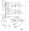
HV power supply schematic
-
LV power supply schematic
-
Vertical input amplifier schematic
-
Vertical output schematic
-
Trigger schematic
-
Timebase schematic
-
Horizontal amplifier schematic
-
Bottom, toward front
-
Bottom, toward rear
-
Attenuators and front-end
-
Right front, sweep rate switch
-
HV power supply
-
Right front
-
Left rear, delay line, LV regulator tubes
-
Left top
-
CRT neck pins
-
Rear right, transformer, filter caps, fan
-
Right top
-
Rear


