11A71: Difference between revisions
No edit summary |
(added pictures (thank you very much Tadej!)) |
||
| Line 2: | Line 2: | ||
title=Tektronix 11A71 | | title=Tektronix 11A71 | | ||
summary=Single channel 1 GHz amplifier | | summary=Single channel 1 GHz amplifier | | ||
image= | image=11a71-ext.jpg | | ||
caption=Tek 11A71 | | caption=Tek 11A71 | | ||
series=[[11000-series scopes]] | | series=[[11000-series scopes]] | | ||
| Line 22: | Line 22: | ||
==Internals== | ==Internals== | ||
Custom Tek chips used: [[155-0175-00]], ... | Custom Tek chips used: [[155-0180-00]], [[155-0181-00]], [[155-0175-00]], [[155-0076-00]], ... | ||
==Links== | ==Links== | ||
| Line 28: | Line 28: | ||
==Pictures== | ==Pictures== | ||
<gallery> | <gallery> | ||
11a71-ext.jpg | 11A71 external view | |||
Tek 11a71 block.png | Block diagram | |||
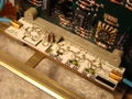
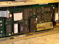
11a71-right.jpg | Right side of the 11A71 plug-in (analog board) | |||
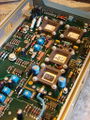
11a71-input.jpg | Input section. Cable loop acts as a delay line, connects to the input attenuator. | |||
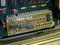
11a71-atten.jpg | Input attenuator, 50 Ω signal path. Laser-trimmed thick film resistors. AC coupling capacitor in plastic support. | |||
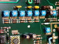
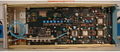
11a71-amp.jpg | Amplifier section. Blue cable from input attenuator connects to the [[155-0180-00|155-0180-00 input protection circuit]]. Signal is differential from after the first amplifier up to the AD converter in the mainframe. | |||
11a71-comp.jpg | Compensation trimmers | |||
11a71-detail.jpg | Close-up of late-80s RF design | |||
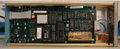
11a71-digital.jpg | Digital board, 8031 MCU | |||
11a71-daughter.jpg | Digital daughter board | |||
Tek 11a71 left.jpg | left side | |||
Tek 11a71 right.jpg | right side | |||
</gallery> | </gallery> | ||
Revision as of 03:15, 3 November 2016
Template:Plugin Sidebar 2 The Tektronix 11A71 a single-channel 1 GHz amplifier for 11000-series scopes.
The 11A71 is derived from the 7A29.
Key Specifications
| Bandwidth | 1 GHz |
|---|---|
| Input impedance | 50 Ω via a Tekprobe BNC connector on the front on the plug-in |
please add
Internals
Custom Tek chips used: 155-0180-00, 155-0181-00, 155-0175-00, 155-0076-00, ...
Links
Pictures
-
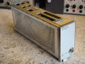
11A71 external view
-
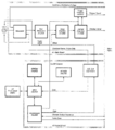
Block diagram
-
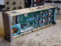
Right side of the 11A71 plug-in (analog board)
-
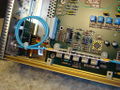
Input section. Cable loop acts as a delay line, connects to the input attenuator.
-
Input attenuator, 50 Ω signal path. Laser-trimmed thick film resistors. AC coupling capacitor in plastic support.
-
Amplifier section. Blue cable from input attenuator connects to the 155-0180-00 input protection circuit. Signal is differential from after the first amplifier up to the AD converter in the mainframe.
-
Compensation trimmers
-
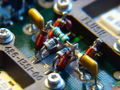
Close-up of late-80s RF design
-
Digital board, 8031 MCU
-
Digital daughter board
-
left side
-
right side


