7D01: Difference between revisions
No edit summary |
No edit summary |
||
| Line 12: | Line 12: | ||
}} | }} | ||
The '''Tektronix 7D01''' is a logic analyzer plug-in for the [[7000-series scopes]]. Compatible extension modules | The '''Tektronix 7D01''' is a logic analyzer plug-in for the [[7000-series scopes]]. Compatible extension modules | ||
include the [[DF1]] and [[DF2]] display formatters and the [[DL2]] latch (glitch detector). | include the [[DF1]] and [[DF2]] display formatters and the [[DL2]] latch (glitch detector). it takes two [[P6451]] 8+1 channel probes. | ||
{{BeginSpecs}} | {{BeginSpecs}} | ||
{{Spec | Channels | | {{Spec | Channels | | ||
* 4 channels at 1016 bits/channel, maximum external clock period | * 4 channels at 1016 bits/channel, maximum external clock period 10 ns (100 MHz) | ||
* 8 channels at 508 bits/channel, maximum external clock period | * 8 channels at 508 bits/channel, maximum external clock period 20 ns (50 MHz) | ||
* 16 channels at 254 bits/channel, maximum external clock period | * 16 channels at 254 bits/channel, maximum external clock period 40 ns (25 MHz) | ||
}} | }} | ||
{{Spec | Sampling Rate | 10 ns to 5 ms per sample (1—2—5) or external clock up to 50 MHz}} | {{Spec | Sampling Rate | 10 ns to 5 ms per sample (1—2—5) or external clock up to 50 MHz}} | ||
{{Spec | | {{Spec | Trigger Sources | | ||
* external | * external | ||
* channel 0 data | * channel 0 data | ||
| Line 28: | Line 28: | ||
}} | }} | ||
{{EndSpecs}} | {{EndSpecs}} | ||
==Notes== | ==Notes== | ||
| Line 43: | Line 42: | ||
<gallery> | <gallery> | ||
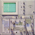
Tek-7704a-7D01.jpg | 7D01 in [[7704A]] mainframe | |||
Tek_7D01_Front.jpg | 7D01+[[DF1]] Front | |||
Tek_7D01_timing.jpg | 7D01 Timing Diagram | |||
Tek_7D01-DF01_timing.jpg | 7D01 + [[DF1]] Timing Diagram | |||
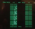
Tek_7D01-DF01_table.jpg | 7D01 + [[DF1]] State Table | |||
Tek_7D01_Left.jpg | 7D01 Left | |||
Tek_7D01_Right.jpg | 7D01 Right | |||
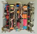
Tek_7D01_Bottom.jpg | 7D01 Bottom | |||
Tek_7D01_rear.jpg | 7D01 Rear (back plate removed) | |||
Tek_7D01_Cursor.jpg | 7D01 Cursor Board | |||
Tek_7D01_Memory.jpg | 7D01 Memory Board | |||
Tek df2 7d01 lit.jpg | Tek df2 7d01 lit.jpg | ||
Revision as of 23:20, 27 May 2017
Template:Plugin Sidebar 2 The Tektronix 7D01 is a logic analyzer plug-in for the 7000-series scopes. Compatible extension modules include the DF1 and DF2 display formatters and the DL2 latch (glitch detector). it takes two P6451 8+1 channel probes.
Key Specifications
| Channels |
|
|---|---|
| Sampling Rate | 10 ns to 5 ms per sample (1—2—5) or external clock up to 50 MHz |
| Trigger Sources |
|
Notes
Note about external clock rates (from Jim Mauck):
When I was a Tek Service Technician I worked on the 7D01. For several years I tested every 7D01 I worked on (and that was a lot of them) with a 100MHz external clock in 16 channel mode. I would use a DF2 and set it to reacquire continuously as long as the 7D01 memory was the same as the original data I stored into the DF2 memory. The analyzer would run for hours without error. The funny part is that it wasn't until I had been doing this for several years that I realized it wasn't specified to run at that frequency. I continued to test them that way even after I discovered my error. However the instrument exceeding the specifications might be due to the data source providing a generous setup and hold time relative to the active clock edge.


