1S1: Difference between revisions
m (Reverted edits by David Wise (talk) to last revision by Peter) |
m (Reverted edits by Peter (talk) to last revision by David Wise) |
||
| Line 5: | Line 5: | ||
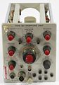
caption=1S1 front view| | caption=1S1 front view| | ||
introduced=1965 | | introduced=1965 | | ||
discontinued= | discontinued=1974 | | ||
series=[[500-series scopes]]| | series=[[500-series scopes]]| | ||
manuals= | manuals= | ||
| Line 18: | Line 18: | ||
and the horizontal voltage from the oscilloscope can be used to control the 1S1, as described below. | and the horizontal voltage from the oscilloscope can be used to control the 1S1, as described below. | ||
The 1S1 has a 50 Ω [[GR-874 connector]] for signal input. The plug-in supplies power (+100 V and -12.6 V) to | The 1S1 has a 50 Ω [[GR-874 connector]] for signal input. The plug-in supplies power (+100 V and -12.6 V) to accessories like the [[P6032]] Cathode Follower Probe, the [[281]] TDR Pulser, and the [[282]] Probe Adapter. | ||
The 1S1 can operate in normal self-swept mode or an external sweep signal can be applied to the 1S1. | The 1S1 can operate in normal self-swept mode or an external sweep signal can be applied to the 1S1. | ||
| Line 24: | Line 24: | ||
so the the 1S1 acts as a lookup table, a mapping of x to y, a function. | so the the 1S1 acts as a lookup table, a mapping of x to y, a function. | ||
The 661 also has this capability, in its "A vert/B horiz" mode, which is like X-Y mode for a sampler. | The 661 also has this capability, in its "A vert/B horiz" mode, which is like X-Y mode for a sampler. | ||
In this mode, the horizontal-in voltage controls | In this mode, the horizontal-in voltage controls the time after the trigger event when the sample should be taken, | ||
and the vertical-out voltage corresponds to the voltage measured at that instant. | and the vertical-out voltage corresponds to the voltage measured at that instant. | ||
This allows a waveform to be digitized using an arbitrarily slow DAC to generate the horizontal voltage | This allows a waveform to be digitized using an arbitrarily slow DAC to generate the horizontal voltage | ||
| Line 39: | Line 39: | ||
The sampler in the 1S1 is quite different from the sampler in the [[1S2]]. The 1S1 uses a [[sampling diodes|four-diode]] sampling bridge, terminated within the 1S1. The 1S2 uses a two-diode feed-through sampler, typical for TDR instruments. | The sampler in the 1S1 is quite different from the sampler in the [[1S2]]. The 1S1 uses a [[sampling diodes|four-diode]] sampling bridge, terminated within the 1S1. The 1S2 uses a two-diode feed-through sampler, typical for TDR instruments. | ||
Type 1S1 was [[introduced in 1965]] and sold through 1973. | Type 1S1 was designed by [[Chuck Edgar]], [[introduced in 1965]] and sold through 1973. | ||
The Type [[282]] Probe Adapter works with the 1S1. | The Type [[282]] Probe Adapter works with the 1S1. | ||
Revision as of 12:04, 29 September 2017
Template:Plugin Sidebar 2 The Tektronix 1S1 is a sampling plug-in for 500-series scopes.
It is essentially one channel of a sampling unit and a timing unit from a 661. It has its own trigger and timebase.
The oscilloscope's timebase is usually set to a relatively slow sweep rate when using a 1S1. Alternatively, the sweep on the oscilloscope can be free-run, and the horizontal voltage from the oscilloscope can be used to control the 1S1, as described below.
The 1S1 has a 50 Ω GR-874 connector for signal input. The plug-in supplies power (+100 V and -12.6 V) to accessories like the P6032 Cathode Follower Probe, the 281 TDR Pulser, and the 282 Probe Adapter.
The 1S1 can operate in normal self-swept mode or an external sweep signal can be applied to the 1S1. With the 1S1's internal sweep disabled, the horizontal-in and vertical-out connections can be used so the the 1S1 acts as a lookup table, a mapping of x to y, a function. The 661 also has this capability, in its "A vert/B horiz" mode, which is like X-Y mode for a sampler. In this mode, the horizontal-in voltage controls the time after the trigger event when the sample should be taken, and the vertical-out voltage corresponds to the voltage measured at that instant. This allows a waveform to be digitized using an arbitrarily slow DAC to generate the horizontal voltage and ADC to read the sampled output. But perhaps more importantly, by setting a constant horizontal-in voltage, it allows the output signal at one equivalent time instant to be processed in the time domain. For example, this allows the voltage to be low-pass filtered, so that it can be more accurately measured. The other reason why one might want a signal that consists of multiple sequential measurements of the same equivalent-time instant is that statistics can be calculated on these observations. For example, one might want to know, when testing a logic gate, what is the propagation delay such that 99.9% of the transitions happen faster than this.
The horizontal-in voltage can also be produced, in "manual" mode, by setting a knob on the 1S1.
The sampler in the 1S1 is quite different from the sampler in the 1S2. The 1S1 uses a four-diode sampling bridge, terminated within the 1S1. The 1S2 uses a two-diode feed-through sampler, typical for TDR instruments.
Type 1S1 was designed by Chuck Edgar, introduced in 1965 and sold through 1973.
The Type 282 Probe Adapter works with the 1S1. It is an active buffer to allow the use of high impedance probes with the 50 ohm input of the 1S1. It does, however, lower the bandwidth.
When the 1S1 is set for INT trigger signal, the EXT TRIG input is terminated with 50 ohms.
Pictures
-
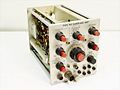
front view
-
-

-
-
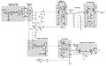
block diagram


