564: Difference between revisions
m (fleshed out caption) |
m (rearrange images images, putting all 564 images before 564B images) |
||
| Line 77: | Line 77: | ||
Tek 564 with viewing hood.jpg|564 with viewing hood on a [[201]] cart | Tek 564 with viewing hood.jpg|564 with viewing hood on a [[201]] cart | ||
Tek 564 with viewing hood2.jpg|564 with viewing hood on a [[201]] cart | Tek 564 with viewing hood2.jpg|564 with viewing hood on a [[201]] cart | ||
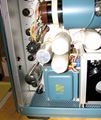
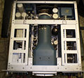
Tek564 left internals 4.jpg|Tektronix 564 Left Internals | |||
Tek564 left internals 5.jpg|Tektronix 564 Left Internals | |||
Tek564 left internals 2.jpg|Tektronix 564 Left Internals | |||
Tek564 left internals 3.jpg|Tektronix 564 Left Internals | |||
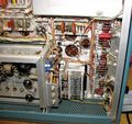
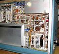
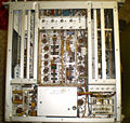
Tek564 right internals 4.jpg|Tektronix 564 Right Internals | |||
Tek564 right internals 5.jpg|Tektronix 564 Right Internals | |||
Tek564 right internals 2.jpg|Tektronix 564 Right Internals | |||
Tek564 right internals 7.jpg|Tektronix 564 Right Internals | |||
Tek564 right internals 6.jpg|Tektronix 564 Right Internals | |||
Tek564 right internals 8.jpg|Tektronix 564 Right Internals | |||
Tek564 right internals 9.jpg|Tektronix 564 Right Internals | |||
Tek_564_HV.jpg | Tektronix 564 HV Section - Cover Removed | |||
</gallery> | |||
====564 Schematics==== | |||
<gallery> | |||
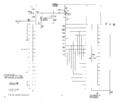
Tek 564 block.png|564 Block Diagram | |||
Tek 564 power supply.png|564 Power Supply | |||
Tek 564 interconnecting sockets.png|564 Interconnecting Sockets | |||
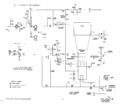
Tek 564 crt circuit.png|564 CRT Circuit | |||
Tek 564 calibrator.png|564 Calibrator | |||
Tek 564 storage circuit.png|564 Storage Circuit | |||
</gallery> | </gallery> | ||
| Line 112: | Line 134: | ||
<gallery> | <gallery> | ||
R564B_1.JPG|R564B w auto-erase and 3A6 and 3B3 | R564B_1.JPG|R564B w auto-erase and 3A6 and 3B3 | ||
</gallery> | </gallery> | ||
Revision as of 17:19, 27 July 2022
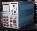
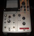
The Tektronix 564 is the storage scope of the 560 series, introduced in June 1962. It takes two 2- or 3-series plug-ins. The RM564 is the rack-mount version.
The 564 is a tube-based oscilloscope, whereas a later version, the 564B (1969), is fully solid state. Mod 121N added auto-erase. The screen has bi-stable storage in two 4 cm × 10 cm sections, allowing independent saving and erasing of the upper and lower half.
The 564 was one of the mainframes offered for the Engine Analyzer package.
Key Specifications
| Bandwidth | Determined by plug-in (up to 25 MHz available) or up to 1 GHz with 3-series sampling plugins |
|---|---|
| Writing speed | ≥25 Div/ms with T5640-200; ≥100 Div/ms with T5640-201 |
| Storage time | At least 1 hour |
| CRT | 8×10 Div @ 1 cm/Div, external graticule; tube 154-0410-00/154-0565-00 (standard, P200) / 154-0418-00/154-0565-01 (fast writing speed, P201); 3.5 kV acceleration |
| Calibrator | 564: 0.2 mV to 100 Vp-p in 18 2-5-10 steps, square wave at line frequency
564B: 4 mV to 40 Vp-p in 5 decade steps, square wave at 1 kHz, plus 40 VDC into high impedance, and 2 mV to 0.2 V into 50 Ohms in 3 decade steps. |
| Power | 105−125 V or 210−250 V, 50 to 400 Hz, Convection cooling, thermal cut-off switch; 564: 250 W maximum; 564B: 196 W maximum |
| Weight | Without plugins: 564 ~13.8 kg (30.5 lbs), 564B ~14.2 kg (31.25 lbs) |
Steve Ditter says:
Tek offered two phosphors for the 564. You can determine which one you have by reading the CRT part number, visible in the window in the shield where the deflection plate connections are. 154-0410-00 is P200, which was the standard tube. The 154-0418-00 is the P201, which has faster writing rate, but at the expense of about 30% shorter useful life.
Links
- Tek 564 / RM564 @ barrytech.com
- J.Evans's 564 page
- Ralph K's 564 pictures page
- A 564 @ YouTube / another one
Internals
As in all 560 series scopes, the left plug-in directly drives the vertical deflection plates of the CRT, and the right plug-in directly drives the horizontal deflection plates.
Accessories
The 012-0102-00 Storage Oscilloscope Control Unit that works with the 549 also works with the 564B but not the 564. It provides (corded) remote reset of the sweep and independent erase of the upper and lower storage areas.
Pictures
564
-
-
-
Tektronix 564 Front Panel
-
564, Display
-
Tektronix 564 Display (in Storage Mode)
-
Tektronix 564 Back
-
Tektronix 564 Left
-
Tektronix 564 Right
-
564 with viewing hood on a 201 cart
-
564 with viewing hood on a 201 cart
-
Tektronix 564 Left Internals
-
Tektronix 564 Left Internals
-
Tektronix 564 Left Internals
-
Tektronix 564 Left Internals
-
Tektronix 564 Right Internals
-
Tektronix 564 Right Internals
-
Tektronix 564 Right Internals
-
Tektronix 564 Right Internals
-
Tektronix 564 Right Internals
-
Tektronix 564 Right Internals
-
Tektronix 564 Right Internals
-
Tektronix 564 HV Section - Cover Removed
564 Schematics
-
564 Block Diagram
-
564 Power Supply
-
564 Interconnecting Sockets
-
564 CRT Circuit
-
564 Calibrator
-
564 Storage Circuit
564 Versions
-
564 version 1
-
564 version 2
-
564 version 3
RM564
-
-
RM564, Switch for storage
-
RM564, Chassis
-
RM564, Chassis bottom
564B
-
564B
-
564B
-
564B
-
564B
564B with Auto Erase, MOD121N
-
564B/MOD121N on cart
R564B
-
R564B w auto-erase and 3A6 and 3B3
Third-party
-
Physionic 671 Ultrasonic Imager, based on 564
-
Physionic 671 Ultrasonic Imager, based on 564
-
Physionic 671 Ultrasonic Imager, based on 564
-
Physionic 671 Ultrasonic Imager, based on 564
-
Physionic 671 Ultrasonic Imager, based on 564
-
Physionic 671 Ultrasonic Imager, based on 564


