661: Difference between revisions
No edit summary |
No edit summary |
||
| Line 1: | Line 1: | ||
The Tektronix 661 is a [[sampling oscilloscope]] that was [[introduced in 1961]]. | The Tektronix 661 is a [[sampling oscilloscope]] that was [[introduced in 1961]]. | ||
It accepts two plug-ins: a sampling unit and a timing unit. | It accepts two plug-ins: a sampling unit and a timing unit. | ||
Four | |||
Four sampling units were made: | |||
* [[4S1]] (0.35 ns rise time) | * [[4S1]] (0.35 ns rise time) | ||
* [[4S2|4S2 and 4S2A]] (0.1 ns rise time) | * [[4S2|4S2 and 4S2A]] (0.1 ns rise time) | ||
| Line 11: | Line 12: | ||
* [[5T3]] | * [[5T3]] | ||
== Inter-module Signals == | |||
The timing units use [[tunnel diodes|tunnel diode]] triggering. | The timing units use [[tunnel diodes|tunnel diode]] triggering. | ||
Two 50-ohm coaxial cables in the scope connect the sampling unit to the timing unit. | Two 50-ohm coaxial cables in the scope connect the sampling unit to the timing unit. | ||
| Line 19: | Line 21: | ||
telling it when to sample. | telling it when to sample. | ||
== Triggering Modes == | |||
A 661 can be triggered in at least four distinct modes: | A 661 can be triggered in at least four distinct modes: | ||
* The 4S1 uses a trigger pickoff transformer to produce the internal trigger signal | * The 4S1 uses a trigger pickoff transformer to produce the internal trigger signal | ||
| Line 28: | Line 31: | ||
* The calibration signal generator in the 661 can be used as trigger source, as described below. | * The calibration signal generator in the 661 can be used as trigger source, as described below. | ||
== Subsystems of the 661 == | |||
Other than the two plug-ins, the 661 mainframe essentially consists of four subsystems: | Other than the two plug-ins, the 661 mainframe essentially consists of four subsystems: | ||
* power supply | * power supply | ||
| Line 34: | Line 38: | ||
* delayed pulse generator | * delayed pulse generator | ||
=== Power Supply === | |||
The power supply is typical of | The power supply is typical of | ||
Tektronix scopes of early 1960s. | Tektronix scopes of early 1960s. | ||
| Line 42: | Line 47: | ||
use BJT-based regulators. The other regulators are tube-based. | use BJT-based regulators. The other regulators are tube-based. | ||
=== Indicator === | |||
The indicator is a conventional X-Y indicator. | The indicator is a conventional X-Y indicator. | ||
The total CRT accelerating voltage is 3kV and | The total CRT accelerating voltage is 3kV and | ||
| Line 50: | Line 56: | ||
that determine their gain. | that determine their gain. | ||
=== Calibrator === | |||
The amplitude/time calibrator is a Colpitts oscillator that uses a [[7119]] | The amplitude/time calibrator is a Colpitts oscillator that uses a [[7119]] | ||
tube. It produces clippped sine waves at frequencies from 100kHz to 100MHz and | tube. It produces clippped sine waves at frequencies from 100kHz to 100MHz and | ||
| Line 59: | Line 66: | ||
In many situations, this eliminates the need for external triggering. | In many situations, this eliminates the need for external triggering. | ||
=== Delayed Pulse Generator === | |||
The delayed pulse generator is a [[tunnel diodes|tunnel diode]] circuit | The delayed pulse generator is a [[tunnel diodes|tunnel diode]] circuit | ||
that produces a negative-going 250mV pulse with a risetime of about 150 ps | that produces a negative-going 250mV pulse with a risetime of about 150 ps | ||
Revision as of 08:09, 7 May 2013
The Tektronix 661 is a sampling oscilloscope that was introduced in 1961. It accepts two plug-ins: a sampling unit and a timing unit.
Four sampling units were made:
- 4S1 (0.35 ns rise time)
- 4S2 and 4S2A (0.1 ns rise time)
- 4S3 (uses P6038 sampling probes)
Three timing units were made:
Inter-module Signals
The timing units use tunnel diode triggering. Two 50-ohm coaxial cables in the scope connect the sampling unit to the timing unit. One of these cables sends the "internal trigger signal" from the sampling unit to the timing unit. The other cable sends the "start sample signal" from the timing unit to the sampling unit, telling it when to sample.
Triggering Modes
A 661 can be triggered in at least four distinct modes:
- The 4S1 uses a trigger pickoff transformer to produce the internal trigger signal
that can trigger the timing unit. The 4S1 is the only 661 sampling unit that produces an internal trigger signal.
- An external trigger signal can be fed to the timing unit via its front panel.
- The timing unit can be operated in in free-running mode and the resulting pulse signal
can be the stimulus for the device under test. This mode is similar to a TDR.
- The calibration signal generator in the 661 can be used as trigger source, as described below.
Subsystems of the 661
Other than the two plug-ins, the 661 mainframe essentially consists of four subsystems:
- power supply
- indicator
- amplitude/time calibration signal generator
- delayed pulse generator
Power Supply
The power supply is typical of Tektronix scopes of early 1960s. An OG3 tube is used as a voltage reference for the +300V supply. The other supply voltages use the +300V supply as their reference. The +19V and -19V supplies use BJT-based regulators. The other regulators are tube-based.
Indicator
The indicator is a conventional X-Y indicator. The total CRT accelerating voltage is 3kV and the vertical and horizontal amplifiers are relatively mild differential amplifiers made of 6DJ8 tubes and OC170 germanium bipolar junction transistors. The vertical and horizontal amplifiers have feedback loops around them that determine their gain.
Calibrator
The amplitude/time calibrator is a Colpitts oscillator that uses a 7119 tube. It produces clippped sine waves at frequencies from 100kHz to 100MHz and amplitudes from 1mV to 1000mV. The output is 50-ohm GR-874. The signal from the calibration generator is available on the front panel and is also sent to the timing generator through the multi-pin plug-in connector. This allows the timing plug-ins to select "CAL" as a trigger source. In this mode, the calibration generator can be used as the stimulus for the device under test. In many situations, this eliminates the need for external triggering.
Delayed Pulse Generator
The delayed pulse generator is a tunnel diode circuit that produces a negative-going 250mV pulse with a risetime of about 150 ps and a pulse width of about 400 ns. The output is 50-ohm GR-874. When a timing unit (e.g., a 5T1) triggers, it sends a pulse through pin 10 of the J4 interconnect to the delayed pulse generator, which regenerates the pulse. There are three versions of the 661 delayed pulse generator. The first is in serial numbers 101 through 2829. The second version is in serial numbers 2830 through 3459. The third version is in serial numbers 3460 and up. All three versions use a 50mA tunnel diode to generate the actual output pulse. The circuit versions differ in how they bias and trip the output tunnel diode.
Based on the available schematics, the 661 appears to have been designed in 1961. During what years was it manufactured? Why is it that the 661 has a dedicated high-speed coaxial interface between the sampling unit the timing unit while later 560-series sampling systems (3S2, 3T77A, etc.) are able to simply use the regular plug-in connector and mainframe wiring harness for routing trigger and timing signals between the two units?
Some 661s have a multipin connector on the rear panel, perhaps to allow the 661 to be interfaced to low speed data acquisition equipment or a computer.
The 661 has a 137°F thermal cutoff. In practice, it doesn't run hot.
- Tektronix 661 Manual (PDF)
- Late Issue Tektronix 661 Manual (PDF)
- 4S1 manual without schematics
- 4S1 schematics
- 4S2 schematics
- 4S2 complete manual
- 5T1A manual
- 5T3 manual
- Tek 661 4S1 5T1 Preliminary Manual (PDF)
- Tektronix 661 Factory Calibration Procedure (PDF)
- http://w140.com/Nucl_Instrum_Methods_TD_Induct_effects_1968.pdf
-
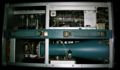
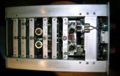
top internal view
-
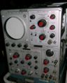
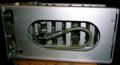
front view
-
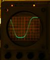
trace with 10 samples/cm and 2x horizontal expansion
-

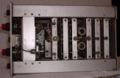
left internal view
-
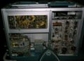
right internal view
-
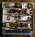
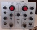
top view of 4S1
-
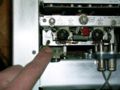
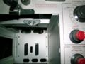
Coaxial interconnect from timing plug-in goes through the mainframe, into the 4S1, and ends here, at the sampler.
-
This is the sampler. The GaAs sampling diodes are arranged in a diamond shape and are directly connected to the socket from the delay line.
-
The delay line is a coil of coax going from the trigger pickoff to the sampler.
-
The 661 mainframe has two pieces of 50-ohm coax that connect the sampling unit bay to the timing unit bay. The plug-ins engage with these interconnects when inserted.
-
4S2 top view
-
4S2 front view


