R293: Difference between revisions
(Per TekWeek Jan 7, 1966) |
No edit summary |
||
| (3 intermediate revisions by 2 users not shown) | |||
| Line 1: | Line 1: | ||
The '''Tektronix R293''' is a pulse generator [[introduced in 1965]] | {{Instrument Sidebar | ||
for use with automated measurement systems such as the [[240]] and [[R250]]. | |manufacturer=Tektronix | ||
|model=R293 | |||
|class=Pulse generator | |||
|series= | |||
|summary=Programmable pulse generator | |||
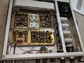
|image=Tek-r293.jpg | |||
|caption=Tek R293 | |||
|introduced=1965 | |||
|discontinued=(?) | |||
|designers=Murlan Kaufman | |||
|manuals= | |||
* [[Media:070-0433-00.pdf|Tektronix R293 Manual]] (PDF) | |||
* [https://w140.com/tek_r293_description.pdf Description of R293 from Tektronix Automated Testing Systems book] (PDF) | |||
* [https://w140.com/tek_r293_1968_catalog.pdf Tektronix R293 in 1968 Catalog] (PDF) | |||
}} | |||
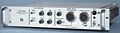
The '''Tektronix R293''' is a pulse generator [[introduced in 1965]] for use with automated measurement systems such as the [[240]] and [[R250]]. | |||
The R293 contains an analog programmable power supply | The task of designing the R293 was inherited and completed by [[Murlan Kaufman]]. | ||
and an analog programmable pulse generator. | |||
The pulse is produced by an avalanche transistor | The R293 contains an analog programmable power supply and an analog programmable pulse generator. | ||
fed through a pulse shaper made of diode clamps | The pulse is produced by an avalanche transistor fed through a pulse shaper made of diode clamps and [[snap-off diode|snap-off diodes]]. | ||
and [[snap-off diode|snap-off diodes]]. | |||
The output pulse amplitude is variable from 6 V to 12 V. | The output pulse amplitude is variable from 6 V to 12 V. | ||
Overshoot of the output pulse is less that 3%, rise and fall time are 1 ns or less. | Overshoot of the output pulse is less that 3%, rise and fall time are 1 ns or less. | ||
The service procedure in the manual specifies the use of a [[661]] | The service procedure in the manual specifies the use of a [[661]] for adjustment of the pulse shaper. | ||
for adjustment of the pulse shaper. | |||
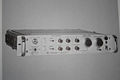
Some instances of the R293 have an RF connector on the front panel | Some instances of the R293 have an RF connector on the front panel while others have all of their connector on the rear panel. | ||
while others have all of their connector on the rear panel. | MOD 703M puts all input and output connectors of the R293 on the rear panel, for use in automated testing systems. | ||
MOD 703M puts all input and output connectors of the R293 on the rear panel, | |||
for use in automated testing systems. | |||
An R293 is normally programmed from an [[R250]]. | An R293 is normally programmed from an [[R250]]. | ||
The power supply output connector mates with a Bendix PC06A-8-4P-SR connector. | |||
* [ | * [[Media:12-070-180554-1158107.pdf|Amphenol Miniature Cylindrical Connectors (PDF)]] | ||
==Pictures== | ==Pictures== | ||
Latest revision as of 12:25, 20 August 2021

The Tektronix R293 is a pulse generator introduced in 1965 for use with automated measurement systems such as the 240 and R250.
The task of designing the R293 was inherited and completed by Murlan Kaufman.
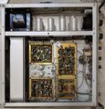
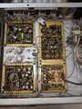
The R293 contains an analog programmable power supply and an analog programmable pulse generator. The pulse is produced by an avalanche transistor fed through a pulse shaper made of diode clamps and snap-off diodes.
The output pulse amplitude is variable from 6 V to 12 V. Overshoot of the output pulse is less that 3%, rise and fall time are 1 ns or less.
The service procedure in the manual specifies the use of a 661 for adjustment of the pulse shaper.
Some instances of the R293 have an RF connector on the front panel while others have all of their connector on the rear panel. MOD 703M puts all input and output connectors of the R293 on the rear panel, for use in automated testing systems.
An R293 is normally programmed from an R250.
The power supply output connector mates with a Bendix PC06A-8-4P-SR connector.
Pictures
-
-
-
-
-
-
Block Diagram
-
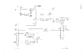
Pulse Generator
-

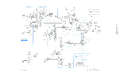
Pulse Shaper
-
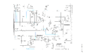
Programmable Power Supply
-
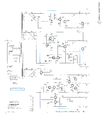
Pulse Generator Power Supply


