S-4: Difference between revisions
mNo edit summary |
No edit summary |
||
| (39 intermediate revisions by 7 users not shown) | |||
| Line 1: | Line 1: | ||
{{Plugin Sidebar | |||
|manufacturer=Tektronix | |||
|series=7000 and 3S series sampling heads | |||
|type=S-4 | |||
|summary=Sampling Head | |||
|image=Tek-s-4.jpg | |||
|caption=S-4 head | |||
|introduced=1968 | |||
|discontinued=1990 | |||
|designers=George Frye | |||
|manuals= | |||
* [[Media:070-0896-00.pdf|Tektronix S-4 Manual 1969]] (OCR) | |||
* [[Media:070-0896-01 march 1985.pdf|Tektronix S-4 Instruction Manual, Revised March 1985]] (OCR) | |||
* [[Media:070-0896-01.pdf|Tektronix S-4 Instruction Manual, Revised October 1986]] (OCR) | |||
* [[Media:Frye s4 gate.pdf|George Frye's Explanation of S-4 sampler in October 1968 Service Scope]] | |||
* [[Media:Tek s-4 fcp april 1969 - OCR.pdf|Tektronix S-4 Factory Calibration Procedure, April 1969]] (OCR) | |||
}} | |||
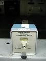
The '''Tektronix S-4''' is a sampling head for 7000- and 3S-series samplers. | |||
It was designed by [[George Frye]] and [[introduced in 1968]]. | |||
It is the fastest of the S-series plug-in samplers. | |||
The | {{BeginSpecs}} | ||
{{Spec | Rise time | 25 ps (35 ps observed with [[S-50]] or [[S-52]]) }} | |||
{{Spec | Bandwidth | 14.5 GHz }} | |||
{{Spec | Input impedance | 50 Ω (terminated [[SMA connector]])}} | |||
{{Spec | Input voltage | 1 V<sub>p-p</sub> (operating) }} | |||
{{Spec | Maximum input | ±5 V max. non-destructive }} | |||
{{Spec | Noise | < 5 mV}} | |||
{{Spec | Features | | |||
* trigger signal pick-off for internal triggering | |||
}} | |||
{{EndSpecs}} | |||
==Internals== | |||
The [[Sampler#Six-Diode_Sampler|S-4 sampling gate]] is based upon a traveling wave trapped-charge transmission line | |||
in which the sampling window is set by the propagation time of a pulse edge through a thick-film transmission line. | |||
This technique requires only a sharp pulse edge rather than a precise pulse width, which is harder to generate. | |||
The sampling diodes are housed in a special coaxial connector that provides a high bandwidth signal path. | The sampling diodes are housed in a special coaxial connector that provides a high bandwidth signal path. | ||
During the development of the S-4, the velocity gate theory was tested using | |||
a length of transmission line between diodes. | |||
This led to an aperture time that depended upon twice the propagation delay of the length of transmission line. | |||
To disassemble the sampler hybrid, first remove it from the sampler board as per the manual. | |||
Remove the input connector using a 7/32" wrench and remove the 20 dB attenuator with small pliers. | |||
The ceramic board is held to the housing using roll pins that can be pressed out with a 0.030" pin punch. | |||
The hybrid has six diodes, each about 0.75 mm². | |||
The cathodes are glued to the gold substrate with conductive epoxy and the anodes | |||
are wire-bonded (twice) over a gap to the next step in the strobe line. | |||
It appears that a standard beam-lead diode may fit across the gap | |||
but cleanly removing a failed diode without damaging the substrate would be quite difficult. | |||
==Prices== | |||
1979: $1,435 (~$6,000 in 2023 dollars) | |||
According to an [[Media:Tek Schottky Diodes Memo rot.pdf|internal memo]], annual sales were estimated at 150 units in 1979. | |||
==Links== | |||
* [http://www.amplifier.cd/Test_Equipment/Tektronix/Tektronix_7000_series_special/S4.html S-4 page @ amplifier.cd] | |||
* [https://kh6htv.files.wordpress.com/2015/11/an-02a-oscopes.pdf James R. Andrews, ''Comparison of Ultra-Fast Rise Sampling Oscilloscopes''. Picosecond Pulse Labs App Note AN-2a, 1989] | |||
==Pictures== | |||
<gallery> | <gallery> | ||
Tek-s-4.jpg | |||
Tek s4.jpg | |||
S4_top.jpg | Top view of the S4 plug-in | |||
S4_left.jpg | Left view | |||
S4_right.jpg |Right view | |||
S4 schem.png | Schematic | |||
Tektronix-S4-sampler-board-strobe.jpg | Sampler board, strobe side | |||
Tektronix-S4-sampler-board-preamp.jpg | Sampler board, preamp side | |||
Tektronix-S4-sampler-board-hybrid.jpg | Sampler board, disassembled with parts orientation | |||
Tektronix-S4-hybrid-internal.jpg | Microphotograph of sampler hybrid | |||
S-4_B15_prototype.JPG | S-4 B-prototype, no difference to standard S-4 | |||
Tek s-4 in 7s11.jpg | S-4 in [[7S11]] | |||
7s11-s4.jpg | S-4 in [[7S11]] | |||
</gallery> | </gallery> | ||
==Parts== | |||
{{Parts|S-4}} | |||
[[Category:7000 and 3S series sampling heads]] | |||
Latest revision as of 06:16, 30 January 2024

The Tektronix S-4 is a sampling head for 7000- and 3S-series samplers. It was designed by George Frye and introduced in 1968. It is the fastest of the S-series plug-in samplers.
Key Specifications
| Rise time | 25 ps (35 ps observed with S-50 or S-52) |
|---|---|
| Bandwidth | 14.5 GHz |
| Input impedance | 50 Ω (terminated SMA connector) |
| Input voltage | 1 Vp-p (operating) |
| Maximum input | ±5 V max. non-destructive |
| Noise | < 5 mV |
| Features |
|
Internals
The S-4 sampling gate is based upon a traveling wave trapped-charge transmission line in which the sampling window is set by the propagation time of a pulse edge through a thick-film transmission line. This technique requires only a sharp pulse edge rather than a precise pulse width, which is harder to generate. The sampling diodes are housed in a special coaxial connector that provides a high bandwidth signal path.
During the development of the S-4, the velocity gate theory was tested using a length of transmission line between diodes. This led to an aperture time that depended upon twice the propagation delay of the length of transmission line.
To disassemble the sampler hybrid, first remove it from the sampler board as per the manual. Remove the input connector using a 7/32" wrench and remove the 20 dB attenuator with small pliers. The ceramic board is held to the housing using roll pins that can be pressed out with a 0.030" pin punch.
The hybrid has six diodes, each about 0.75 mm². The cathodes are glued to the gold substrate with conductive epoxy and the anodes are wire-bonded (twice) over a gap to the next step in the strobe line. It appears that a standard beam-lead diode may fit across the gap but cleanly removing a failed diode without damaging the substrate would be quite difficult.
Prices
1979: $1,435 (~$6,000 in 2023 dollars)
According to an internal memo, annual sales were estimated at 150 units in 1979.
Links
- S-4 page @ amplifier.cd
- James R. Andrews, Comparison of Ultra-Fast Rise Sampling Oscilloscopes. Picosecond Pulse Labs App Note AN-2a, 1989
Pictures
-

-
-
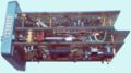
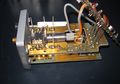
Top view of the S4 plug-in
-
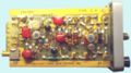
Left view
-
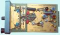
Right view
-
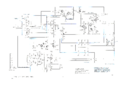
Schematic
-
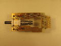
Sampler board, strobe side
-
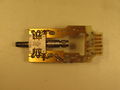
Sampler board, preamp side
-
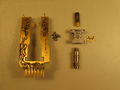
Sampler board, disassembled with parts orientation
-
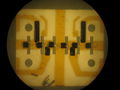
Microphotograph of sampler hybrid
-
S-4 B-prototype, no difference to standard S-4
-
S-4 in 7S11
-
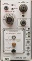
S-4 in 7S11


Parts
Some Parts Used in the S-4
| Part | Part Number(s) | Class | Description | Used in |
|---|---|---|---|---|
| 152-0335-00 | 152-0335-00 | Discrete component | step recovery diode | S-4 • S-6 |
| 152-0335-01 | 152-0335-01 | Discrete component | 150 ps step recovery diode | 1502 • S-2 • S-4 • S-6 |
| 155-0001-00 | 155-0001-00 | Hybrid integrated circuit | gate assembly | S-4 |