105: Difference between revisions
No edit summary |
No edit summary |
||
| (14 intermediate revisions by 2 users not shown) | |||
| Line 1: | Line 1: | ||
[[ | {{Instrument Sidebar | ||
The '''Tektronix 105''' is a 25 Hz to 1 MHz square wave generator. | |manufacturer=Tektronix | ||
It | |model=105 | ||
|class=Signal generator | |||
|series= | |||
|summary=25 Hz to 1 MHz square wave generator | |||
|image=Tek_105_front.jpg | |||
|caption= | |||
|introduced=1950 | |||
|discontinued=(?) | |||
|designers=Howard Vollum;Charles Sanford | |||
|manuals= | |||
* [[Media:070-049.pdf|Tektronix 105 Manual]] | |||
* [[Media:Tek type 105 field recal proc.pdf|Tektronix 105 Field Recalibration Procedure]] (OCR) | |||
* [[Media:Tek 105 fcp.pdf|Tektronix 105 Factory Calibration Procedure]] (OCR) | |||
}} | |||
The '''Tektronix 105''' is a 25 Hz to 1 MHz square-wave generator. | |||
It was designed by [[Howard Vollum]] and [[Charles Sanford]] and has an all-tube construction. | |||
The 105 has a d'Arsonval meter on its front panel indicating the current frequency. | The 105 has a d'Arsonval meter on its front panel indicating the current frequency. | ||
The frequency meter works on the principle of moving a constant amount of charge per cycle, integrating this charge into a current, and measuring the current. | The frequency meter works on the principle of moving a constant amount of charge per cycle, integrating this charge into a current, and measuring the current. | ||
The output is generated at the plates of three [[6AG7]] triodes that run in parallel. | |||
{{BeginSpecs}} | |||
{{Spec|Frequency|25 Hz to 1 MHz}} | |||
{{Spec|Rise and fall time|20 ns (10% to 90%) }} | |||
{{Spec|Amplitude|10 V to 100 V<sub>p-p</sub> (internal 600 Ω load); 1.5 V to 15 V<sub>p-p</sub> (external 93 Ω load) }} | |||
{{Spec|Power|250 W}} | |||
{{Spec|Weight|35 pounds}} | |||
{{EndSpecs}} | |||
==Pictures== | ==Pictures== | ||
| Line 38: | Line 48: | ||
Tek 105 power supply.png|Power supply schematic | Tek 105 power supply.png|Power supply schematic | ||
Tek 105 generator and meter.png|Generator schematic | Tek 105 generator and meter.png|Generator schematic | ||
Early tek 105.jpg|Early Tek 105 with horizontal case | |||
Tek 105 early power light low.jpg|Early Tek 105 with power light below switches | |||
</gallery> | </gallery> | ||
==Components== | |||
{{Parts|105}} | |||
[[Category:Pulse generators]] | [[Category:Pulse generators]] | ||
Latest revision as of 06:45, 18 June 2024
The Tektronix 105 is a 25 Hz to 1 MHz square-wave generator. It was designed by Howard Vollum and Charles Sanford and has an all-tube construction.
The 105 has a d'Arsonval meter on its front panel indicating the current frequency. The frequency meter works on the principle of moving a constant amount of charge per cycle, integrating this charge into a current, and measuring the current.
The output is generated at the plates of three 6AG7 triodes that run in parallel.
Key Specifications
| Frequency | 25 Hz to 1 MHz |
|---|---|
| Rise and fall time | 20 ns (10% to 90%) |
| Amplitude | 10 V to 100 Vp-p (internal 600 Ω load); 1.5 V to 15 Vp-p (external 93 Ω load) |
| Power | 250 W |
| Weight | 35 pounds |
Pictures
-
105 front
-
Early style of 105 with blocky meter
-
-
-
-
manual
-
powered on
-
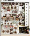
internal view, tube side
-
right interior
-
output section detail
-
output waveform of 105
-
Block diagram
-
Power supply schematic
-
Generator schematic
-
Early Tek 105 with horizontal case
-
Early Tek 105 with power light below switches
Components
Some Parts Used in the 105
| Part | Part Number(s) | Class | Description | Used in |
|---|---|---|---|---|
| 6AG7 | 154-012 • 154-0012-00 | Vacuum Tube (Pentode) | 9 Watt power pentode | 104 • 104A • 105 • 112 • 511 • 511A • 512 • 513 • 514 • 517 • 517A • 524 |
| 6CB6A | 154-0030-00 | Vacuum Tube (Pentode) | pentode | 105 • 112 • 316 • 317 • 503 • 504 • 513 • 517 • 517A • 541 • 535 • 545 • 63 • 2A63 |


