571: Difference between revisions
No edit summary |
No edit summary |
||
| (19 intermediate revisions by 3 users not shown) | |||
| Line 10: | Line 10: | ||
|discontinued=1995 | |discontinued=1995 | ||
|manuals= | |manuals= | ||
* [[Media:070-7723-01.pdf|Tektronix 571 Operator's Manual -01]] | * [[Media:070-7723-01.pdf | Tektronix 571 Operator's Manual -01]] | ||
* [[Media:070-7723-00.pdf|Tektronix 571 Operator's Manual -00]] | * [[Media:070-7723-00.pdf | Tektronix 571 Operator's Manual -00]] | ||
* [[Media:070-7722-00.pdf|Tektronix 571 Service Manual]] | * [[Media:070-7722-00.pdf | Tektronix 571 Service Manual]] | ||
{{ROM Images}} | |||
}} | }} | ||
The '''Tektronix 571''' is a [[:Category:Curve tracers|curve tracer]]. | The '''Tektronix 571''' is a [[:Category:Curve tracers|curve tracer]]. | ||
| Line 19: | Line 20: | ||
A typical sweep run takes about five seconds. It has a parallel printer output that can print graphics on Epson-protocol dot-matrix printers. | A typical sweep run takes about five seconds. It has a parallel printer output that can print graphics on Epson-protocol dot-matrix printers. | ||
The 571 can store a set of ''reference'' curves, which are displayed as a background for subsequent measurement runs. | |||
This | This helps the operator compare and match devices. | ||
The 571 has a | The 571 has a field of parallel-connected sockets to accommodate many different semiconductor package types. | ||
Details can be seen in the photographs below. | Details can be seen in the photographs below. | ||
Because | Because electronic component testing sometimes involves exposing components to hazardous voltages and operating conditions, | ||
at certain settings the 571 will refuse to start a measurement cycle until the user lowers the built-in hinged plastic shield over the socket area. | at certain settings the 571 will refuse to start a measurement cycle until the user lowers the built-in hinged plastic shield over the socket area. | ||
This is to protect the user from both high voltage and high-velocity flying debris in the event of a catastrophic component failure during a test run. | This is to protect the user from both high voltage and high-velocity flying debris in the event of a catastrophic component failure during a test run. | ||
The shield is made of a thick high-impact plastic, and the 571 has an internal microswitch so its firmware knows if the shield is in the up or down position. | The shield is made of a thick high-impact plastic, and the 571 has an internal microswitch so its firmware knows if the shield is in the up or down position. | ||
{{BeginSpecs}} | |||
{{Spec | Collector Sweep | 0.5 V to 50 V (both polarities) with 2 A drive, 0.5 V to 100 V with 1 A drive }} | |||
{{Spec | Vertical Display | plots collector current from 5 μA per division to 200 mA per division with 2% accuracy }} | |||
{{Spec | Horizontal Display | plots collector voltage with 2% accuracy }} | |||
{{Spec | CRT | raster scan, 640x336 resolution, monochrome, magnetic deflection, CRT made by Philips }} | |||
{{Spec | Line voltage | 100 to 240 V<sub>AC</sub>, 50 or 60 Hz }} | |||
{{Spec | Power | 240 W max − Actual consumption based on transistor being tested }} | |||
{{Spec | Size | (W/L/H) 14.6" × 13.8" × 8.1" }} | |||
{{Spec | Weight | 9 kg (19.8 lb) }} | |||
{{EndSpecs}} | |||
==Internals== | ==Internals== | ||
The Tektronix 571 is a computer-based instrument. | The Tektronix 571 is a computer-based instrument. | ||
Software running in an Intel | Software running in an [[Intel 8032]] microcontroller performs the I-V curve measurements by sending commands to programmable base and collector power supplies, | ||
by sending commands to programmable base and collector power supplies, | |||
and reading the digitized that results. | and reading the digitized that results. | ||
Software provides the user interface, reading the buttons and generating the displayed bitmap. | Software provides the user interface, reading the buttons and generating the displayed bitmap. | ||
The 571 uses an National Semiconductor NS405 Display/Terminal Management Processor IC for generating the | The 571 uses an National Semiconductor NS405 Display/Terminal Management Processor IC for generating the video waveform that is displayed. | ||
video waveform that is displayed. | |||
The video waveform is fed to a monochrome raster CRT monitor. | The video waveform is fed to a monochrome raster CRT monitor. | ||
Power (not DUT current) and digital control signals pass through a pair of 14-conductor ribbon cables | |||
that connect the mainboard to the collector supply board and the front panel board. | |||
These two ribbon cables use AMP (now known as TE) [[Micro-Match]] connectors. | |||
===Collector Supply=== | ===Collector Supply=== | ||
| Line 46: | Line 59: | ||
An Analog Devices DAC08 DAC, which is floating along with the rest of the collector supply, | An Analog Devices DAC08 DAC, which is floating along with the rest of the collector supply, | ||
generates the programmable collector voltage. | generates the programmable collector voltage. | ||
The | The DAC value sent by the microprocessor passes through an octal optoisolator before being fed to the DAC. | ||
The collector supply is linear, basically a discrete power op-amp. | The collector supply is linear, basically a discrete power op-amp. | ||
The output stage is a Darlington configuration of three NPN transistors. | The output stage is a Darlington configuration of three NPN transistors. | ||
When supplying | When supplying 2 A to the DUT at 0.5 V, the power dissipation in the collector supply output transistors is around 100 watts. | ||
is around 100 watts. | In contrast, curve tracers that use rectified mains frequency from a transformer, e.g., the [[576]], dissipate very little internally even while supplying high current to the DUT. | ||
In contrast, curve tracers that use rectified mains frequency from a transformer, e.g., the [[576]], | |||
dissipate very little internally even while supplying high current to the DUT. | |||
== | ===CRT=== | ||
The 571 uses a [[Media:Philips m24-306 308 310 328 datasheet.pdf|Philips M24-306GH/ED]] 9 inch monochrome (green) CRT, Tektronix part number 119-3795-00. It is possible that Tek bought the CRT and its associated power supply and deflection circuitry as a single OEM module. | |||
===ROMs and Programmable Logic Devices=== | |||
There are three 27256 ROMs on the 571 Main Board: | |||
* U502 V1.1 160-6993-01 (software for the 8032) | |||
* U503 V1.6 160-6992-06 (software for the 8032) | |||
* U607 V1.1 160-6991-01 (software for the NS405) | |||
ROM image files for all three ROMs can be found on the [[ROM images]] page. | |||
There are two smaller decoder chips in 20-pin DIP (300mil) packages, likely to be 16V8 GAL/PAL: | |||
* U507 160-7046-00 | |||
* U509 160-7045-00 | |||
These are soldered in. | |||
The 571 contains an [[NMC98C10]] EEPROM that it uses for storing menu settings. | |||
The EEPROM has twelve locations, each of which can store all of the menu settings | |||
for a particular measurement, e.g., kind of device, max voltage, number of base steps, etc. | |||
==Links== | |||
* [https://www.youtube.com/watch?v=Ays64LxEc5w 571 Run Through] from Craig Peterson @ YouTube | |||
==Pictures== | ==Pictures== | ||
| Line 82: | Line 101: | ||
Tek 571 npn.jpg | Tek 571 npn.jpg | ||
</gallery> | </gallery> | ||
==Parts== | |||
{{Parts|571}} | |||
[[Category:Curve tracers]] | [[Category:Curve tracers]] | ||
Latest revision as of 03:28, 20 July 2024

The Tektronix 571 is a curve tracer. It can show the characteristic curves of PNP and NPN bipolar transistors, both N- and P-channel FETs, diodes (including Zener types), and SCRs. It is a microprocessor-controlled device, and user interaction is done through navigation keys. A typical sweep run takes about five seconds. It has a parallel printer output that can print graphics on Epson-protocol dot-matrix printers.
The 571 can store a set of reference curves, which are displayed as a background for subsequent measurement runs. This helps the operator compare and match devices.
The 571 has a field of parallel-connected sockets to accommodate many different semiconductor package types. Details can be seen in the photographs below.
Because electronic component testing sometimes involves exposing components to hazardous voltages and operating conditions, at certain settings the 571 will refuse to start a measurement cycle until the user lowers the built-in hinged plastic shield over the socket area. This is to protect the user from both high voltage and high-velocity flying debris in the event of a catastrophic component failure during a test run. The shield is made of a thick high-impact plastic, and the 571 has an internal microswitch so its firmware knows if the shield is in the up or down position.
Key Specifications
| Collector Sweep | 0.5 V to 50 V (both polarities) with 2 A drive, 0.5 V to 100 V with 1 A drive |
|---|---|
| Vertical Display | plots collector current from 5 μA per division to 200 mA per division with 2% accuracy |
| Horizontal Display | plots collector voltage with 2% accuracy |
| CRT | raster scan, 640x336 resolution, monochrome, magnetic deflection, CRT made by Philips |
| Line voltage | 100 to 240 VAC, 50 or 60 Hz |
| Power | 240 W max − Actual consumption based on transistor being tested |
| Size | (W/L/H) 14.6" × 13.8" × 8.1" |
| Weight | 9 kg (19.8 lb) |
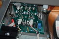
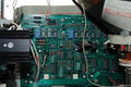
Internals
The Tektronix 571 is a computer-based instrument. Software running in an Intel 8032 microcontroller performs the I-V curve measurements by sending commands to programmable base and collector power supplies, and reading the digitized that results. Software provides the user interface, reading the buttons and generating the displayed bitmap. The 571 uses an National Semiconductor NS405 Display/Terminal Management Processor IC for generating the video waveform that is displayed. The video waveform is fed to a monochrome raster CRT monitor. Power (not DUT current) and digital control signals pass through a pair of 14-conductor ribbon cables that connect the mainboard to the collector supply board and the front panel board. These two ribbon cables use AMP (now known as TE) Micro-Match connectors.
Collector Supply
The collector supply is a floating programmable regulated power supply. The control and data signals entering the collector supply are isolated by relays and optoisolators. The output voltage, output polarity, and series resistance are all set by bits sent by the 8048 processor. An Analog Devices DAC08 DAC, which is floating along with the rest of the collector supply, generates the programmable collector voltage. The DAC value sent by the microprocessor passes through an octal optoisolator before being fed to the DAC. The collector supply is linear, basically a discrete power op-amp. The output stage is a Darlington configuration of three NPN transistors. When supplying 2 A to the DUT at 0.5 V, the power dissipation in the collector supply output transistors is around 100 watts. In contrast, curve tracers that use rectified mains frequency from a transformer, e.g., the 576, dissipate very little internally even while supplying high current to the DUT.
CRT
The 571 uses a Philips M24-306GH/ED 9 inch monochrome (green) CRT, Tektronix part number 119-3795-00. It is possible that Tek bought the CRT and its associated power supply and deflection circuitry as a single OEM module.
ROMs and Programmable Logic Devices
There are three 27256 ROMs on the 571 Main Board:
- U502 V1.1 160-6993-01 (software for the 8032)
- U503 V1.6 160-6992-06 (software for the 8032)
- U607 V1.1 160-6991-01 (software for the NS405)
ROM image files for all three ROMs can be found on the ROM images page.
There are two smaller decoder chips in 20-pin DIP (300mil) packages, likely to be 16V8 GAL/PAL:
- U507 160-7046-00
- U509 160-7045-00
These are soldered in.
The 571 contains an NMC98C10 EEPROM that it uses for storing menu settings. The EEPROM has twelve locations, each of which can store all of the menu settings for a particular measurement, e.g., kind of device, max voltage, number of base steps, etc.
Links
- 571 Run Through from Craig Peterson @ YouTube
Pictures
-
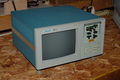
571, front 3/4 view
-
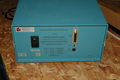
571, rear view
-
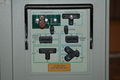
571, measurement head, shield up
-
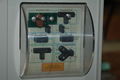
571, measurement head, shield down
-
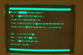
571, parameters screen
-
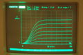
571, run of a 2N2222A transistor
-
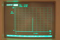
571, run of a 1N3020B 10V Zener diode
-
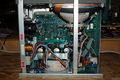
571, inside view
-
571, inside view, closeup of socket board
-
571, inside view, closeup of relays
-


Parts
Some Parts Used in the 571
| Part | Part Number(s) | Class | Description | Used in |
|---|---|---|---|---|
| Intel 8031 | Monolithic integrated circuit | 8-bit microcontroller | 11A33 • 571 • DM504A • DM511 • DM5110 | |
| Intel 8032 | Monolithic integrated circuit | 8-bit microcontroller | 571 | |
| NMC98C10 | Monolithic integrated circuit | 128×8 EEPROM | 571 |