Ceramic strips: Difference between revisions
No edit summary |
No edit summary |
||
| (12 intermediate revisions by 3 users not shown) | |||
| Line 1: | Line 1: | ||
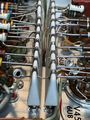
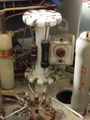
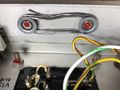
[[File:Tek ceramic strips 6.jpg|thumb|350px|right|Tek ceramic strips]] | |||
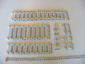
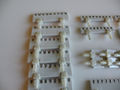
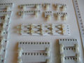
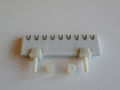
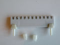
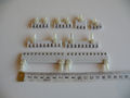
Some Tektronix instruments use '''ceramic strips with metallized grooves''' to hold components and wiring. | Some Tektronix instruments use '''ceramic strips with metallized grooves''' to hold components and wiring. | ||
This started with the [[315|Type 315]] in 1952. | This started with the [[315|Type 315]] in 1952 – Tektronix engineer [[Frank Hood]] recollects: | ||
<blockquote> | |||
such as the [[7514]] mainframe and [[7A18]] vertical plug- | Another employee, [[Ted Goodfellow]], a musician with ceramics as a hobby, suggested making a ceramic strip with silvered notches to act as insulator and support for the components. | ||
</blockquote> | |||
The use of ceramic strips continued into the early 7000-series instruments such as the [[7514]] mainframe, [[7A15A]] and [[7A18]] vertical plug-ins, | |||
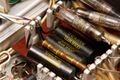
all of which were [[introduced in 1971]]. A late example is the [[465B]] from 1980 that uses these strips in the HV section. | |||
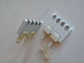
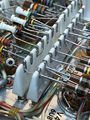
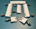
Two distinct types of rectangular ceramic strips have been used in Tektronix instruments. | |||
The earlier wedge type used a nut and bolt to mount it to the chassis (see illustrations in [[Patent US 2836807A|US Patent 2,836,807]] which also include the [[Media:Tek_524_round_terminal_strip.jpg|cylindrical variety]] used in the [[524]]). | |||
The later rectangular style uses plastic snap-in clips (see [[Patent US 3022973A|US Patent 3,022,973]]). | |||
The production method is discussed in [[Patent US 3121020A|US Patent #3,121,020]]. | |||
[[File:Tek ceramic strip soldering.jpg|thumb|350px|right|Soldering instructions (click to enlarge)]] | |||
The ceramic strips | The ceramic strips turned out to be quite reliable. | ||
If they aren't abused, the only known failure mode is when they are used in HV supplies | If they aren't abused, the only known failure mode is when they are used in HV supplies and are allowed to get very dirty. | ||
and are allowed to get very dirty. | The dirt can become conductive, resulting in unintended current flow over the surface of the ceramic strip, silver migration, and/or arcing. | ||
The dirt can become conductive, resulting in unintended current flow | Once arcing occurs, heat from the arc would fire the silver into the ceramic, causing a permanent short that cannot be reliably cleared – such a strip must be replaced. | ||
over the surface of the ceramic strip, and/or arcing. | |||
This can be avoided by keeping the HV circuit clean, particularly the nodes after the rectifier(s). | This can be avoided by keeping the HV circuit clean, particularly the nodes after the rectifier(s). | ||
Tektronix warned that | ==Soldering considerations== | ||
Tektronix warned that their ceramic strips should only be soldered with silver-bearing solder (3% Ag was recommended). | |||
From [[502]] manual [[Media:070-090.pdf|070-090]] (1959), page 5-2: | From [[502]] manual [[Media:070-090.pdf|070-090]] (1959), page 5-2: | ||
| Line 45: | Line 54: | ||
==Links== | ==Links== | ||
* [https://vintagetek.org/ceramic-strips/ VintageTEK: Ceramic Strips and Funnels] | |||
* [https://www.youtube.com/watch?v=RpB5JqGo1co Tektronix video: Ceramic Strip Soldering Techniques] | * [https://www.youtube.com/watch?v=RpB5JqGo1co Tektronix video: Ceramic Strip Soldering Techniques] | ||
* [[Media: | * [[Media:Ceramic_Strips-PartNo.pdf| Tek Part Number Reference (pdf)]] | ||
{{PatentLinks|Ceramic Strips}} | |||
==Pictures== | ==Pictures== | ||
<gallery> | <gallery> | ||
Tek ceramic strips overview and part numbers.jpg | Tek ceramic strips - overview and part numbers | |||
Tek ceramic strips 1.jpg | Tek ceramic strips 1.jpg | ||
Tek ceramic strips 2.jpg | Tek ceramic strips 2.jpg | ||
| Line 58: | Line 70: | ||
Tek ceramic strips 6.jpg | Tek ceramic strips 6.jpg | ||
Tek ceramic strips 7.jpg | Tek ceramic strips 7.jpg | ||
Tek Ceramic strip-old.jpeg | Earlier model ceramic strip | |||
Tek Ceramic-strip-old2.jpeg | Earlier model ceramic strip | |||
Tek Ceramic-strip-early-used.jpeg | Earlier model ceramic strip (used) | |||
585 HV - Black Beauty.jpg|Ceramic strips in [[585]] HV section | |||
Tek_524_round_terminal_strip.jpg | Cylindrical strip used in the [[524]] and [[C|53/54C]] | |||
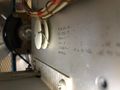
Tek_547-Silver-Solder1.jpg | Silver Solder Spool inside a Tek 547 #1 | Tek_547-Silver-Solder1.jpg | Silver Solder Spool inside a Tek 547 #1 | ||
Tek_547-Silver-Solder2.jpg | Silver Solder Spool inside a Tek 547 #2 | Tek_547-Silver-Solder2.jpg | Silver Solder Spool inside a Tek 547 #2 | ||
Spare solder.jpg | |||
Tek_Lead-Spool.jpeg | Earlier type solder spool inside a Tek 130 | |||
</gallery> | </gallery> | ||
[[Category:Repair issues]] | [[Category:Repair issues]] | ||
Latest revision as of 03:59, 8 June 2024

Some Tektronix instruments use ceramic strips with metallized grooves to hold components and wiring. This started with the Type 315 in 1952 – Tektronix engineer Frank Hood recollects:
Another employee, Ted Goodfellow, a musician with ceramics as a hobby, suggested making a ceramic strip with silvered notches to act as insulator and support for the components.
The use of ceramic strips continued into the early 7000-series instruments such as the 7514 mainframe, 7A15A and 7A18 vertical plug-ins, all of which were introduced in 1971. A late example is the 465B from 1980 that uses these strips in the HV section.
Two distinct types of rectangular ceramic strips have been used in Tektronix instruments. The earlier wedge type used a nut and bolt to mount it to the chassis (see illustrations in US Patent 2,836,807 which also include the cylindrical variety used in the 524). The later rectangular style uses plastic snap-in clips (see US Patent 3,022,973). The production method is discussed in US Patent #3,121,020.

The ceramic strips turned out to be quite reliable. If they aren't abused, the only known failure mode is when they are used in HV supplies and are allowed to get very dirty. The dirt can become conductive, resulting in unintended current flow over the surface of the ceramic strip, silver migration, and/or arcing. Once arcing occurs, heat from the arc would fire the silver into the ceramic, causing a permanent short that cannot be reliably cleared – such a strip must be replaced. This can be avoided by keeping the HV circuit clean, particularly the nodes after the rectifier(s).
Soldering considerations
Tektronix warned that their ceramic strips should only be soldered with silver-bearing solder (3% Ag was recommended). From 502 manual 070-090 (1959), page 5-2:
Soldering Precautions
In the production of Tektronix instruments, a special silver-bearing solder is used to establish a bond to the ceramic terminal strips. This bond may be broken by repeated use of ordinary tin-lead solder, or by the application of too much heat. However, occasional use of ordinary solder will not break the bond if too much heat is not applied.
It is advisable that you have a stock of solder containing about 3% silver if you frequently perform work on Tektronix instruments. This type of solder is used quite often in printed circuitry and should be readily available. It may also be purchased directly from Tektronix in one-pound rolls (order by part number 251-514).
Because of the shape of the terminals on the ceramic terminal strips you may wish to use a wedge-shaped tip on your soldering iron. A tip such as this allows you to apply heat directly to the solder in the terminals thereby reducing the heat required to melt the solder. Since excessive heat can destroy the bond of the terminal to the ceramic material, it is important to use as little heat as possible. Also, the wedge-shaped tip is desirable from a convenience stand-point, since it is easier to work on the ceramic strips with this type of tip.
Early instruments often contained a small spool of suitable solder inside the cabinet.
Today, some suitable solder types containing silver, e.g. Sn62Pb36Ag2 (2% silver content, 179°C melting point), are still available.
Competitors like Lavoie used less sensitive tin-plated steel inserts that can be soldered with ordinary solder.
Links
- VintageTEK: Ceramic Strips and Funnels
- Tektronix video: Ceramic Strip Soldering Techniques
- Tek Part Number Reference (pdf)
Patents that may apply to Ceramic Strips
| Page | Title | Inventors | Filing date | Grant date | Links |
|---|---|---|---|---|---|
| Patent US 2836807A | Ceramic terminal mount | Ted Goodfellow • Robert J Davis | 1953-04-20 | 1958-05-27 | Ceramic Strips |
| Patent US 3121020A | Coating method and apparatus for notches and other surface discontinuities | Robert Low | 1960-05-31 | 1964-02-11 | Ceramic strips |
Pictures
-
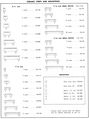
Tek ceramic strips - overview and part numbers
-
-
-
-
-
-
-
-
Earlier model ceramic strip
-
Earlier model ceramic strip
-
Earlier model ceramic strip (used)
-
Ceramic strips in 585 HV section
-
-
Silver Solder Spool inside a Tek 547 #1
-
Silver Solder Spool inside a Tek 547 #2
-
-
Earlier type solder spool inside a Tek 130


