D: Difference between revisions
No edit summary |
No edit summary |
||
| Line 8: | Line 8: | ||
series=500-series scopes | | series=500-series scopes | | ||
manuals= | manuals= | ||
* [[Media:070-228.pdf|Tektronix Type D Manual]] (PDF, OCR, bad-OCR) | |||
* [[Media:070-228.pdf|Tektronix Type D Manual (PDF, OCR, bad-OCR) | |||
* [[Media:tek_type_d_fcp.pdf|Tektronix Type D Factory Calibration Procedure (PDF, OCR)]] | * [[Media:tek_type_d_fcp.pdf|Tektronix Type D Factory Calibration Procedure (PDF, OCR)]] | ||
* [[Media:Tek type d cal outline.pdf|Tektronix Type D Calibration Outline (PDF, OCR)]] | * [[Media:Tek type d cal outline.pdf|Tektronix Type D Calibration Outline (PDF, OCR)]] | ||
<!-- * [http://w140.com/tek_fcp/tek_type_d_factory_cal_proc.pdf Cal procedure] | |||
* [http://bama.edebris.com/manuals/tek/d/ Type D manual @ BAMA] --> | |||
}} | }} | ||
The '''Tektronix Type D''' is a differential amplifier plug-in for [[500-series scopes]]. | The '''Tektronix Type D''' is a differential amplifier plug-in for [[500-series scopes]]. | ||
| Line 23: | Line 21: | ||
This scheme would be reprised in Type [[W]]. | This scheme would be reprised in Type [[W]]. | ||
It displays the difference between two input signals, with a common-mode rejection ratio of 10,000. It has | It displays the difference between two input signals, with a common-mode rejection ratio of 10,000. | ||
six tubes, on a shock-mounted subchassis to avoid microphonics. | It has six tubes, on a shock-mounted subchassis to avoid microphonics. | ||
Along with Types [[A]], [[B]], and [[C]], Type D was introduced with the [[531]] and [[535]] in [[introduced in 1954|1954]]. | Along with Types [[A]], [[B]], and [[C]], Type D was introduced with the [[531]] and [[535]] in [[introduced in 1954|1954]]. | ||
| Line 39: | Line 37: | ||
==Internals== | ==Internals== | ||
Instruments below serial number 3462 used a pair of [[5814]] tubes at the input; later production used [[12AU7]]'s. | Instruments below serial number 3462 used a pair of [[5814]] tubes at the input; later production used [[12AU7]]'s. | ||
These two tube types have different heater currents, and because the heaters are | These two tube types have different heater currents, and because the heaters are series-wired, you cannot switch from one type to the other without circuit modification. | ||
series-wired, you cannot switch from one type to the other without circuit modification. | |||
{{BeginSpecs}} | {{BeginSpecs}} | ||
Revision as of 14:20, 18 August 2021
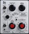
The Tektronix Type D is a differential amplifier plug-in for 500-series scopes.
Type D was the most sensitive plug-in of the original four. The bandwidth depends on the gain, ranging from 2 MHz at 50 mV/div to 300 kHz at 1 mV/div. There are two axes of sensitivity setting: a decade attenuator in front of a gain switch. This scheme would be reprised in Type W.
It displays the difference between two input signals, with a common-mode rejection ratio of 10,000. It has six tubes, on a shock-mounted subchassis to avoid microphonics.
Along with Types A, B, and C, Type D was introduced with the 531 and 535 in 1954.
At the time it was called Type 53D. It was briefly renamed 53D/54D in 1955 with the introduction of the 541 and 545. This quickly changed to 53/54D, and finally shortened to just "D" in 1959 with the introduction of the 5xxA scopes. Its final year in the catalog was 1968; it had been superseded by Type 1A7 and 1A6.
K, L, and T are tied for longest production life, at 16 years. B, D, and G are next at 15 years.
Lavoie Laboratories produced an unauthorized clone, the Lavoie LA-265-D.
Internals
Instruments below serial number 3462 used a pair of 5814 tubes at the input; later production used 12AU7's. These two tube types have different heater currents, and because the heaters are series-wired, you cannot switch from one type to the other without circuit modification.
Key Specifications
| Deflection | 1 mV/Div to 50 V/Div in 1–2–5-10-20-50 sequence and 1-10-100-1000 sequence |
|---|---|
| Input impedance | 1 MΩ // 47 pF (either input) |
| Bandwidth | 2 MHz with MV/CM MULTIPLIER set to 50; 300kHz with MV/CM MULTIPLIER set to 1 |
| CMRR | 10000:1 with MILLIVOLTS/CM set to 1, 1000:1 otherwise |
| Signal ranges |
| Range | Common mode dynamic range* |
|---|---|
| MILLIVOLTS/CM = 1 | ±2.5 V |
| MILLIVOLTS/CM = 10 | ±25 V |
| MILLIVOLTS/CM = 100 | ±250 V |
| MILLIVOLTS/CM = 1000 | ±500 V |
- In practice, Type D behaves well up to about +/-15V if the CM signal is either a brief excursion or a constant. If the CM varies slowly, DC shift in the input tubes will degrade CMRR.
Pictures
-
-
Front
-
Chassis
-
Rubber support for elimination of microphonics
-
Chassis bottom
-
Early Schematic
-
Late Schematic
-
Late Attenuators
-
Front View (vertical position knob not original)


