2465: Difference between revisions
Jump to navigation
Jump to search
No edit summary |
No edit summary |
||
| Line 39: | Line 39: | ||
==Pictures== | ==Pictures== | ||
===2465=== | |||
<gallery> | |||
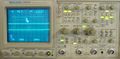
tek2465.jpg | 2465 | |||
Tek 2465 main board 1.jpg |2465 Main Board | |||
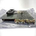
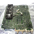
Tek 2465 main board 2.jpg | | |||
Tek 2465 main board 3.jpg | | |||
</gallery> | |||
===2465A=== | |||
<gallery> | |||
Tek2465A.jpg | 2465A | |||
Tek 2465a 1.jpg| | |||
Tek 2465a 2.jpg| | |||
Tek 2465a 3.jpg| | |||
Tek 2465a 4.jpg| | |||
Tek 2465a 5.jpg| | |||
</gallery> | |||
===2465B=== | |||
<gallery> | <gallery> | ||
Tek 2465b trace1.jpg |2465B (photo by Alex Schonfeld) | |||
Tek 2465b trace2.jpg |2465B (photo by Alex Schonfeld) | |||
Tek 2465b trace3.jpg |2465B (photo by Alex Schonfeld) | |||
Tek 2465b trace4.jpg |2465B (photo by Alex Schonfeld) | |||
Tek 2465b trace1.jpg|2465B (photo by Alex Schonfeld) | |||
Tek 2465b trace2.jpg|2465B (photo by Alex Schonfeld) | |||
Tek 2465b trace3.jpg|2465B (photo by Alex Schonfeld) | |||
Tek 2465b trace4.jpg|2465B (photo by Alex Schonfeld) | |||
Tek 2465b trace5.jpg|2465B (photo by Alex Schonfeld) | Tek 2465b trace5.jpg|2465B (photo by Alex Schonfeld) | ||
</gallery> | |||
===2465BDV=== | |||
Tek 2465bdv 1.jpg|2465BDV | <gallery> | ||
Tek 2465bdv 3.jpg|2465BDV | Tek 2465bdv 1.jpg | 2465BDV | ||
Tek 2465bdv 2.jpg|2465BDV | Tek 2465bdv 3.jpg | 2465BDV | ||
Tek 2465bdv 4.jpg|2465BDV | Tek 2465bdv 2.jpg | 2465BDV | ||
Tek 2465bdv 4.jpg | 2465BDV | |||
</gallery> | </gallery> | ||
[[Category:246x series scopes]] | [[Category:246x series scopes]] | ||
Revision as of 09:22, 25 June 2018

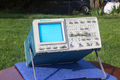
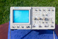
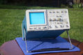
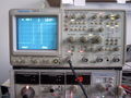
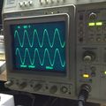
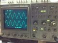
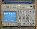
The Tektronix 2465 is a four-channel 300 MHz portable oscilloscope. The 2465A is a 350 MHz scope and the 2465B is the 400 MHz version.
It is the same as the 2467, except that the 2465 uses a conventional CRT while the 2467 uses a micro-channel plate CRT.
The 2465 is from the penultimate generation of analog Tektronix scopes.
Options
- Option 01 (DMM) added a 4 ½digit, fully autoranging digital multimeter which measures DC and AC voltage and current, resistance, dBV, dBm, continuity, and temperature.
- Option 05 (TV) added TV (back-porch) clamp circuitry to the Channel 2 input and TV trigger coupling modes, allowing selection of either horizontal or vertical sync pulses to obtain horizontal-line-sync or field-sync pulse triggering.
- Option 09 added an input for a P6407 Word Recognizer Probe.
- Option 06 (Counter/Timer/Trigger) allows precision time-interval measurement, event and frequency counting, delay-by-events triggering, and logic triggering.
- Option 09 added option 06 plus a 17-bit Word Recognizer probe (P6407).
- Option 10 added a GPIB interface for remote control.
- Option 11 added two probe-power connectors on the rear panel of the instrument.
Key Specifications
- please add
Links
- Tek 2465B page @ amplifier.cd
- Tektronix 2465B oscilloscope teardown @ EEVblog forum (lots of nice internal pictures)
- How to enter test mode
Pictures
2465
-

2465
-
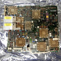
2465 Main Board
-
-


2465A
-
2465A
-
-
-
-
-
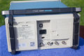


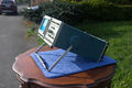
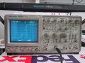
2465B
-
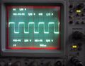
2465B (photo by Alex Schonfeld)
-

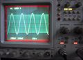
2465B (photo by Alex Schonfeld)
-
2465B (photo by Alex Schonfeld)
-
2465B (photo by Alex Schonfeld)
-
2465B (photo by Alex Schonfeld)


2465BDV
-
2465BDV
-
2465BDV
-
2465BDV
-
2465BDV


