11A71: Difference between revisions
No edit summary |
No edit summary |
||
| Line 14: | Line 14: | ||
The 11A71 is derived from the [[7A29]]. | The 11A71 is derived from the [[7A29]]. | ||
However, the 7A29 has a VARIABLE gain control | However, the 7A29 has a VARIABLE gain control while the 11A71 does not, it has only the 1-2-5 gain sequence. | ||
while the 11A71 does not. | |||
The 7A29 and 11A71 have virtually the same analog circuitry including a Gilbert multiplier at the front end, | The 7A29 and 11A71 have virtually the same analog circuitry including a Gilbert multiplier at the front end, | ||
but in the 11A71 it is only used for automatic calibration, not for fine gain control. | but in the 11A71 it is only used for automatic calibration, not for fine gain control. | ||
This is feature regression, but it avoids an issue that the 7A29 has | This is feature regression, but it avoids an issue that the 7A29 has, namely that its bandwidth changes substantially with the setting of the front panel VARIABLE VOLTS/DIV control. | ||
After calibration, there is a small imbalance in the | After calibration, there is a small imbalance in the 10 mV/div setting, about 0.05 div. | ||
This is a design flaw. | This is a design flaw. | ||
{{BeginSpecs}} | {{BeginSpecs}} | ||
Revision as of 05:34, 18 July 2018
Template:Plugin Sidebar 2 The Tektronix 11A71 a single-channel 1 GHz amplifier for 11000-series scopes.
The 11A71 is derived from the 7A29. However, the 7A29 has a VARIABLE gain control while the 11A71 does not, it has only the 1-2-5 gain sequence.
The 7A29 and 11A71 have virtually the same analog circuitry including a Gilbert multiplier at the front end, but in the 11A71 it is only used for automatic calibration, not for fine gain control. This is feature regression, but it avoids an issue that the 7A29 has, namely that its bandwidth changes substantially with the setting of the front panel VARIABLE VOLTS/DIV control.
After calibration, there is a small imbalance in the 10 mV/div setting, about 0.05 div. This is a design flaw.
Key Specifications
| Bandwidth | DC to 1 GHz |
|---|---|
| Number of Inputs | 1 |
| Rise time | 350 ps in 1 GHz mainframe such as the 11402, 11402A. 11403, 11403A, DSA601A, or DSA602A |
| Deflection | 1 mV/Div to 1 V/Div in 1−2−5 sequence |
| Input impedance | 50 Ω via a Tekprobe BNC connector on the front on the plug-in |
| Features |
|
Internals
Custom Tek chips used: 155-0180-00, 155-0181-00, 155-0175-00, 155-0076-00, ...
Links
Pictures
-
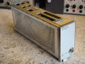
11A71 external view
-
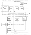
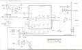
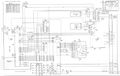
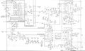
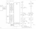
Block diagram
-
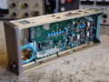
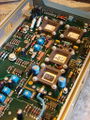
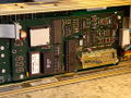
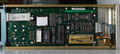
Right side of the 11A71 plug-in (analog board)
-
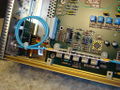
Input section. Cable loop acts as a delay line, connects to the input attenuator.
-
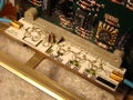
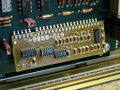
Input attenuator, 50 Ω signal path. Laser-trimmed thick film resistors. AC coupling capacitor in plastic support.
-
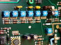
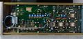
Amplifier section. Blue cable from input attenuator connects to the 155-0180-00 input protection circuit. Signal is differential from after the first amplifier up to the AD converter in the mainframe.
-
Compensation trimmers
-
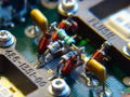
Close-up of late-80s RF design
-
Digital board, 8031 MCU
-
Digital daughter board
-
Attenuator
-
Kernel
-
Amplifier
-
Interface
-
left internal
-
right internal


