1A7A: Difference between revisions
(Removed redirect to 1A7) Tag: Removed redirect |
(split off 1A7A from 1A7 page (redesigned, different specs, different designer)) |
||
| Line 3: | Line 3: | ||
|series=500-series scopes | |series=500-series scopes | ||
|type=1A7A | |type=1A7A | ||
|summary= | |summary=1 MHz differential amplifier | ||
|image=Tek 1a7a 1.JPG | |image=Tek 1a7a 1.JPG | ||
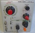
|caption=1A7A | |caption=1A7A | ||
| Line 10: | Line 10: | ||
|designers=Thor Hallen | |designers=Thor Hallen | ||
|manuals= | |manuals= | ||
* [[Media:070-0782-00.pdf|Tektronix 1A7A Manual]] | |||
* [[Media:Tek 1a7a product reference book.pdf|Tektronix 1A7A Product Reference Book]] | |||
* [[Media:Tek 1a7a fcp april 1968.pdf|Tektronix 1A7A Factory Calibration Procedure, April 1968]] | |||
}} | }} | ||
The '''Tektronix 1A7A''', designed by [[Thor Hallen]] and [[introduced in 1968]], is a redesign of the [[1A7]] high-sensitivity differential plug-in for [[500-series scopes]]. | |||
It senses down to 10 μV/Div, either AC or DC-coupled. | |||
The 1A7A doubled the 1A7's bandwidth (to 1 MHz). It has a FET-equipped input stage. | |||
[[Category: | The 1A7A's differential amplifier design was re-used with some modifications | ||
in the [[3A9]], [[3A10]], [[7A22]], [[5A22N]] and [[5030]]/[[5031]] scopes. The [[AM502]] and [[26A2]] use BJTs instead of JFETs for the offset current sources. | |||
Type 1A7A remained available until the end of the [[500-series scopes|500-series]] line. | |||
<blockquote> | |||
[[John Addis]] [[Preamble DA1855|says]]: | |||
The 1A7A (designed by Thor Hallen) and the [[7A22]] (designed by [[Val Garuts]]) used essentially the same circuit. Exactly who came up with the brilliant input circuit is lost to history. The 1A7A came out first, but Thor had worked as evaluation engineer for Val Garuts. Val does not remember who created the circuit, and Thor died in 2002. | |||
</blockquote> | |||
{{BeginSpecs}} | |||
{{Spec | Deflection | 10 μV/Div to 10 V/Div in 1–2–5 sequence }} | |||
{{Spec | Input impedance | 1 MΩ // 47 pF (either input) }} | |||
{{Spec | Bandwidth | 1 MHz, LF limit switchable DC, 0.1 Hz to 10 kHz in ×10 steps, HF limit switchable 100 Hz to 1 MHz in ×3/×10 steps, AC coupling 1.6 Hz }} | |||
{{Spec | Signal ranges | }} | |||
{| class="wikitable" border=1 style="margin-left: 8em;" | | |||
!Range | |||
! Differential signal | |||
! DC Offset | |||
! Common mode | |||
|- | |||
| 10 μV/Div to 10 mV/Div || ±0.4 V || ±0.4 V || ±10 V | |||
|- | |||
| 20 mV/Div to 0.1 V/Div || ±4 V || ±4 V || ±100 V | |||
|- | |||
| 0.2 V/Div to 1 V/Div || ±40 V || ±40 V || ±500 V | |||
|- | |||
| 2 V/Div to 10 V/Div || ±400 V || ±400 V || ±500 V | |||
|- | |||
|} | |||
{{EndSpecs}} | |||
==Pictures== | |||
<gallery> | |||
Tek 1a7a 1.JPG| | |||
Tek 1a7a bf.jpg| | |||
Tek 1a7a 2.JPG| | |||
Tek 1a7a 3.JPG| | |||
Tek 1a7a 4.JPG| | |||
Tek 1a7a 5.JPG| | |||
Tek 1a7a 6.JPG| | |||
</gallery> | |||
[[Category:500 series plugins]] | |||
[[Category:Differential amplifiers]] | |||
Revision as of 11:58, 10 April 2023
The Tektronix 1A7A, designed by Thor Hallen and introduced in 1968, is a redesign of the 1A7 high-sensitivity differential plug-in for 500-series scopes. It senses down to 10 μV/Div, either AC or DC-coupled.
The 1A7A doubled the 1A7's bandwidth (to 1 MHz). It has a FET-equipped input stage.
The 1A7A's differential amplifier design was re-used with some modifications in the 3A9, 3A10, 7A22, 5A22N and 5030/5031 scopes. The AM502 and 26A2 use BJTs instead of JFETs for the offset current sources.
Type 1A7A remained available until the end of the 500-series line.
The 1A7A (designed by Thor Hallen) and the 7A22 (designed by Val Garuts) used essentially the same circuit. Exactly who came up with the brilliant input circuit is lost to history. The 1A7A came out first, but Thor had worked as evaluation engineer for Val Garuts. Val does not remember who created the circuit, and Thor died in 2002.
Key Specifications
| Deflection | 10 μV/Div to 10 V/Div in 1–2–5 sequence |
|---|---|
| Input impedance | 1 MΩ // 47 pF (either input) |
| Bandwidth | 1 MHz, LF limit switchable DC, 0.1 Hz to 10 kHz in ×10 steps, HF limit switchable 100 Hz to 1 MHz in ×3/×10 steps, AC coupling 1.6 Hz |
| Signal ranges |
| Range | Differential signal | DC Offset | Common mode |
|---|---|---|---|
| 10 μV/Div to 10 mV/Div | ±0.4 V | ±0.4 V | ±10 V |
| 20 mV/Div to 0.1 V/Div | ±4 V | ±4 V | ±100 V |
| 0.2 V/Div to 1 V/Div | ±40 V | ±40 V | ±500 V |
| 2 V/Div to 10 V/Div | ±400 V | ±400 V | ±500 V |


