500 Series plug-in interface

The plug-in interface of the 500-series scopes is a single 16-pin Amphenol connector.
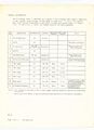
Pin-out
Pin group function legend
|
Internal Trigger signal In early 500-series systems (e.g., a Type C plug-in in a 535 mainframe), the mainframe's triggering is based on the main vertical signal (pins 1/3). In these scopes, changing the vertical position control on the plug-in interacts with the trigger level setting if the scope is set to a DC trigger mode. In somewhat later 500-series systems (e.g. Type 547), the plug-in (e.g. Type 1A1) provides the mainframe with a separate trigger signal on pin 5 whose DC level is not affected by the vertical position knob. In multi-trace setups, this allows consistent triggering from a specific input channel independent of which channel is currently being drawn on CRT. For backward compatibility, the 547-era scopes have two types of INT triggering, taking the trigger signal either from the main vertical plug-in output (1/3), or the trigger output (5). Although the Type 1A1 has two input channels, they are not identical - the pin 5 internal trigger signal is always taken from channel 1. Even later 500-series plug-ins (e.g., the Type 1A4), have a knob for the selection of which input channel's signal supplies the trigger signal. |
-
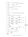
pinout shown in 556 schematic
-
pinout listed in 040-0065-00 kit docs
-
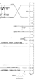
pinout shown in 1A2 schematic
-
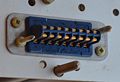
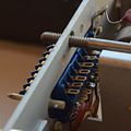
Male pins on plugin
-
Rear lugs on plugin


