240: Difference between revisions
No edit summary |
No edit summary |
||
| (8 intermediate revisions by 2 users not shown) | |||
| Line 1: | Line 1: | ||
[[ | {{Instrument Sidebar | ||
|manufacturer=Tektronix | |||
|model=240 | |||
|class=Controller | |||
|series= | |||
|summary=Program Control Unit | |||
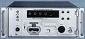
|image=Tek_240_front.jpg | |||
|caption=Tek 240 front | |||
|introduced=1968 | |||
|discontinued=(?) | |||
|designers= | |||
|manuals= | |||
* [[Media:070-0749-00.pdf|Tektronix 240 Manual]] (OCR) | |||
* [https://w140.com/tek_240_r250_description.pdf 240 and R250 Description from Tektronix Automated Testing Systems book] | |||
* [[Media:Tek 240-250 fcp april 1969.pdf|Tektronix 240-250 Factory Calibration Procedure, April 1969]] (OCR) | |||
}} | |||
The '''Tektronix 240''' is a pre-[[GPIB]] "Program Control Unit" [[introduced in 1968]] for the Tektronix [[568]] scope and [[230]] readout. | The '''Tektronix 240''' is a pre-[[GPIB]] "Program Control Unit" [[introduced in 1968]] for the Tektronix [[568]] scope and [[230]] readout. | ||
| Line 7: | Line 22: | ||
The 240 is able to advance sequentially through program steps stored on either the paper tape or disk unit, with basic program control flow (stop or branch) available, driven by the status of the limit indicators on the 230. Each test can be programmed to occur once or twice, in order to minimize the chance of errors due to transients. Each test contains the address of the next test, and a branch status simply adds one to that address. Through J302, addressing functions can be monitored and controlled; presumably more advanced program flow control could be implemented using a computer. | The 240 is able to advance sequentially through program steps stored on either the paper tape or disk unit, with basic program control flow (stop or branch) available, driven by the status of the limit indicators on the 230. Each test can be programmed to occur once or twice, in order to minimize the chance of errors due to transients. Each test contains the address of the next test, and a branch status simply adds one to that address. Through J302, addressing functions can be monitored and controlled; presumably more advanced program flow control could be implemented using a computer. | ||
The address of the test program on disc is a four-digit decimal number set by the DISC TEST ADDRESS switches on the panel of the 240. | |||
The first digit corresponds to the head number on the disc drive. | |||
The other three digits correspond to the sector number. | |||
==Links== | |||
{{Documents|Link=240}} | |||
==See Also== | ==See Also== | ||
* [[020-0025-00]] Disc for use with the Tektronix 240 and 250 | |||
* [[012-0131-00|012-0131-00 Interconnecting Cable]] | * [[012-0131-00|012-0131-00 Interconnecting Cable]] | ||
* [[012-0135-00|012-0135-00 Triangle Interconnecting Cable]] | * [[012-0135-00|012-0135-00 Triangle Interconnecting Cable]] | ||
==Pictures== | ==Pictures== | ||
| Line 28: | Line 46: | ||
</gallery> | </gallery> | ||
[[Category:Controllers]] | [[Category:Controllers]] | ||
Latest revision as of 17:53, 9 March 2024

The Tektronix 240 is a pre-GPIB "Program Control Unit" introduced in 1968 for the Tektronix 568 scope and 230 readout.
The 240 can execute programs from an optional magnetic disk or paper tape, for example as installed in the S-3130 testing station.
The 240 is essentially a 192 bit shift register, generally organized in 4 bit characters. Alone, it is able to completely control the plug-ins of a 568, and the type 230 Read-Out Unit. The output can be expanded to up to 576 bits with the addition of 2 Type R250 Program Control Units, to allow it to control other instruments such as the R116 or R293 pulse generators. With just one 240, there are 14 spare bits that can be used for controlling other components.
The 240 is able to advance sequentially through program steps stored on either the paper tape or disk unit, with basic program control flow (stop or branch) available, driven by the status of the limit indicators on the 230. Each test can be programmed to occur once or twice, in order to minimize the chance of errors due to transients. Each test contains the address of the next test, and a branch status simply adds one to that address. Through J302, addressing functions can be monitored and controlled; presumably more advanced program flow control could be implemented using a computer.
The address of the test program on disc is a four-digit decimal number set by the DISC TEST ADDRESS switches on the panel of the 240. The first digit corresponds to the head number on the disc drive. The other three digits correspond to the sector number.
Links
Documents Referencing 240
| Document | Class | Title | Authors | Year | Links |
|---|---|---|---|---|---|
| Service scope dec 1968 ocr.pdf | Article | Digital Systems Come of Age | John Bowne | 1968 | 3T5 • 3T6 • 3S5 • 3S6 • S-1 • S-2 • S-3 • S-4 • 568 • 230 • 240 • 241 • 250 |
| Tekscope 1970 V2 N4 Aug 1970.pdf | Article | Automated Measurement Systems | 1970 | S-3150 • 568 • 230 • S-3110 • 241 • 240 |
See Also
- 020-0025-00 Disc for use with the Tektronix 240 and 250
- 012-0131-00 Interconnecting Cable
- 012-0135-00 Triangle Interconnecting Cable
Pictures
-
catalog page
-
front panel
-

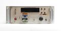
front panel closeup
-
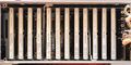
front inside
-
front panel rear
-
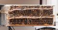
branch card


