7D14: Difference between revisions
No edit summary |
No edit summary |
||
| Line 80: | Line 80: | ||
7d14-input-amp.jpg | 7D14 detail - input amplifier | 7d14-input-amp.jpg | 7D14 detail - input amplifier | ||
7d14-gate.jpg | 7D14 detail - counter gate | 7d14-gate.jpg | 7D14 detail - counter gate | ||
7d14-div2.jpg | 7D14 detail - 525 MHz divide-by-2 stage | 7d14-div2.jpg | 7D14 detail - 525 MHz divide-by-2 stage (later 670-0993-01 board) | ||
7d14-div5.jpg | 7D14 detail - divide-by-5 discrete ring counter stage | 7d14-div5.jpg | 7D14 detail - divide-by-5 discrete ring counter stage | ||
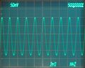
7d14-screen.jpg | 7D14 screen picture - 500 MHz signal counted on trigger path ([[7A19]] amplifier, [[7B92A]] time base in a [[7904]] mainframe) | 7d14-screen.jpg | 7D14 screen picture - 500 MHz signal counted on trigger path ([[7A19]] amplifier, [[7B92A]] time base in a [[7904]] mainframe) | ||
Revision as of 10:41, 4 October 2021

The Tektronix 7D14 is a 525 MHz frequency counter plug-in for 7000 series mainframes.
It uses the mainframe's readout system to display an eight-digit count on the CRT. Modes include frequency, frequency ratio and events count using manual or external gate.
When installed in a horizontal compartment, it can count the trigger pickoff from a vertical amplifier unit. This allows simultaneous viewing and counting of a signal in four-bay mainframes.
In a vertical compartment, the trigger signal (i.e. the "shaped" input) can be displayed as the module's Y output.
Key Specifications
| Frequency | 525 MHz (5 MHz bandwidth limiting switch available) |
|---|---|
| Sensitivity | 100 mV to 10 V |
| Input Impedance | 50 Ω or 1 MΩ // 20 pF on external input, 1.5 Div internal when set to "Trig Source" |
| Gate time | 1 ms to 10 s |
| Display time | 0.1 s to 5 s or infinite |
| Features |
|
Internals
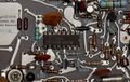
An input section using relays selects the counter signal from the internal trigger path or external input, and activates 50 Ω termination and/or attenuators.
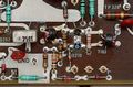
A differential FET buffer + bipolar amplifier stage drives a counter gate that uses a 10 mA tunnel diode as the switching element.
The first decade is implemented as a divide-by-2 ECL flip-flop (156-0377-00) followed by a 5-stage ring counter made with discrete transistor pairs (note circular layout) and some logic to BCD-encode the count result.
The following seven counter stages are conventional TTL decade ripple counters (N8292A).
The counter outputs are multiplexed onto a common 4-bit bus using open-collector NAND gates under control of the mainframe's readout system. The multiplexed digit value feeds a D/A converter (Tek 155-0038-01) that in turn drives the analog row and column returns to the readout system. A separate blanking logic eliminates leading zeroes and displays a ">" sign in the leftmost column if the counter overflows.
In early 7D14 units (board 388-1825-00), U329 was a Tek made IC, 155-0046-00, which was not used in other instruments. From SN B050000 on, an MC12090P was used on a redesigned circuit board (670-0993-01).
Links
Prices
| Year | 1973 | 1976 | 1980 |
|---|---|---|---|
| Price | $1,400 | $1,550 | $2,075 |
| In 2021 Dollars | $8,600 | $7,450 | $6,900 |
Pictures
-
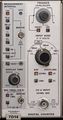
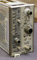
7D14 front panel. The unit pictured was able to count up to 640 MHz on the external input and 532 MHz on the trigger path (7A19 in 7904).
-
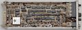
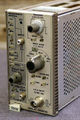
7D14 left side
-
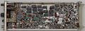
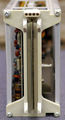
7D14 right side (later 670-0993-01 board)
-

7D14 detail - input amplifier
-
7D14 detail - counter gate
-
7D14 detail - 525 MHz divide-by-2 stage (later 670-0993-01 board)
-

7D14 detail - divide-by-5 discrete ring counter stage
-
-
-
-


Custom ICs used in the 7D14
| Page | Model | Part nos | Description | Designers | Used in |
|---|---|---|---|---|---|
| 155-0038-01 | 155-0038-01 | 155-0038-00 • 155-0038-01 | 5-bit current source D/A converter | Mike Metcalf | 7A42 • 7D13 • 7D14 • 7M13 • T4005 |
| 155-0046-00 | 155-0046-00 | 155-0046-00 | high-speed divider | Luis Navarro | 7D14 |