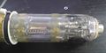
Distributed deflection plates


In conventional CRTs, a trade/off exists between acceleration voltage, deflection sensitivity and frequency response.
As signal frequency increases, the acceleration voltage needs to be increased as well in order to achieve sufficient beam brightness. This in turn reduces deflection sensitivity. To increase sensitivity again, the deflection plates need to be made longer, however, because the electron beam has a finite speed, making the plates too long means that by the time the beam reaches the end of the plate, the driving voltage is already out of phase compared to the time the beam entered the deflection plate structure. In other words, when the drive voltage was going up at the time the beam entered the plate area, by the time it is leaving, the drive voltage will be going down again, pushing the beam back to the center, i.e. sensitivity for higher frequencies falls off sharply.
One solution to this problem is to segment the deflection plates into multiple pairs, each driven by a signal delayed just long enough to match the speed of the electron beam passing trough the segmented structure. This is achieved through a delay line, typically a lumped-constant line built into the tube, where coils are placed between the plate segments, and the plate segments form constant capacitances.

The end of this delay line needs to be terminated to prevent the drive signal being reflected back through the line. In Tektronix scopes, the termination resistor can often be seen attached to a second pair of vertical deflection terminals on the side of the CRT, which bring out the end of the transmission line.
Distributed deflection plates reduce the capacitance seen by the driving amplifier, however, the terminated transmission line presents a much lower impedance than unterminated capacitive plates would. While better matched to semiconductor amplifiers, driving low impedances from tube amplifiers presented challenges, as cathode followers were not able to provide sufficient bandwidth. The problem was solved - at quite some expense - by using a distributed amplifier.
History
Distributed deflection plates were introduced in the 580-series scopes in the late 1950s. Transistorized scopes followed with the upgrade of the 50 MHz 453 to the 150 MHz model 454 in 1967.
Typically, only the vertical deflection plates are distributed. An exception is the 7104 due to the high horizontal system bandwidth required (350 MHz).
| Model | Distributed Y plates | Distributed X plates |
|---|---|---|
| 465 | no | no |
| 475 | ? | no |
| 485 | ? | no |
| 519 | yes | no |
| 53x | no | no |
| 54x | no | no |
| 55x | no | no |
| 56x | no | no |
| 58x | yes | no |
| 7403 | no | no |
| 7503 | no | no |
| 7504 | no | no |
| 7603 | no | no |
| 7612D | ? | ? |
| 7704 | yes | no |
| 7704A | yes | no |
| 7844 | yes | no |
| 7854 | yes | no |
| 7903 | yes | no |
| 7904 | yes | no |
| 7904A | yes | no |
| 7912 | yes | no |
| 7103 | yes | yes |
| 7104 | yes | yes |
Literature
- US Patent 2,922,074, "Electron Beam Deflection Structure" by Cliff Moulton
- Peter Keller, The Cathode-Ray Tube: Technology, History, and Applications, . Palisades Press, 1991. ISBN 0963155903, 9780963155900
- Oscilloscope Cathode-Ray Tube Concepts, Chuck Devere, 1969
-
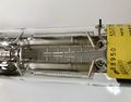
Distributed deflection plates in 154-0850-01 CRT (2445,2455)
-
-
Deflection system of 519 scope


