454
The Tektronix 454 is a 150 MHz portable dual-trace scope designed by Oliver Dalton and introduced in March 1967. It can be seen as an improved 453. The successor 454A was introduced in 1971.

The 454 is the fastest general-purpose Tektronix scope that does not use proprietary hybrid or integrated circuits. It uses a CRT with distributed vertical deflection plates.
Key Specifications
| Bandwidth | 150 MHz (454: 100 MHz @ 10 mV/div, 60 MHz @ 5 mV/div; 454A: 100 MHz @ 5 mV/div, 50 MHz @ 2 mV/div) |
|---|---|
| Deflection | 5 mV/div to 10 V/div; 1−2−5; 454A: additional 2 mV/div |
| Sweep | 50 ns/div (454A: 20 ns/div) to 5 s/div (1−2−5) plus ×10 magnifier, and variable; timebase B to 50 ms/div |
| CRT | T4540, P31 phosphor standard / P11 optional; +12/–1.96 kV acceleration |
| Weight | 13 kg / 29 lb |
| Power | 90–136/180−272 V, 48−440 Hz, 100–145 W |
It is possible to cascade the CH1/CH2 input amplifiers to obtain a sensitivity of 1 mV/Div (454A: 400 μV/div) at a bandwidth of 33 MHz.
The 454 has two ±12 V probe power outputs for P6045 probes.
Links
Documents Referencing 454
| Document | Class | Title | Authors | Year | Links |
|---|---|---|---|---|---|
| Service Scope 43 Apr 1967.pdf | Article | New From Tektronix, Inc. In 1967 | 1967 | 568 • 230 • 454 • 647A • C-40 • 1A4 • 1A5 • 3L5 • 200-1 | |
| Service Scope 49 Apr 1968.pdf | Article | Quick Check for Tunnel Diodes | Tony Bryan | 1968 | Tunnel diodes • 454 |
| Service Scope 49 Apr 1968.pdf | Article | Developing a Writing Speed Specification | 1968 | 454 • C-31 | |
| Service Scope 51 Aug 1968.pdf | Article | Plug-on Versatility | Cal Hongel | 1968 | 323 • P6048 • P6035 • 454 |
Documents Referencing 454A
| Document | Class | Title | Authors | Year | Links |
|---|---|---|---|---|---|
| Tekscope 1971 V3 N2.pdf | Article | New Portables | 1971 | 324 • 453A • 454A | |
| Tekscope 1971 V3 N3 May 1971.pdf | Article | The New Portables | 1971 | 453A • 454A |
Patents that may apply to 454
| Page | Title | Inventors | Filing date | Grant date | Links |
|---|---|---|---|---|---|
| Patent US 3453403A | Power selection device | Eldon Hoffman | 1966-08-18 | 1969-07-01 | 115 • 140 • 141 • 141A • 144 • 145 • 146 • 147 • 148 • 149 • 149A • 230 • 284 • 286 • 453 • 454 • 491 • 520A • 521A • 522 • 545B • 547 • 556 • 561B • 564B • 568 • 576 • 611 • 647A • 2101 • 2601 • 5030 • R5030 • 5031 • R5031 • 7503 • 7504 • 7704 • 7704A • 7904 • R7903 |
Internals
The 454 has a 140 ns delay line in the signal path after the input channel switching and before the main vertical amplifier. There is a phase equalizer after the delay line to mitigate the harm done to pulse fidelity by the delay line.
To not have the need of an additional 6V heater supply for the 6 nuvistors built into the 454, the two existing +12 V and -12 V rails are tapped for this purpose to supply 8393 Nuvistors with a 13.5V nominal heater voltage.
Vertical Preamplifier, the attenuators, vertical display switching and positioning is mounted to a common subassembly with the Vertical preamplifier PCA. Thus, servicing any part of the vertical input section requires extensive removal and desoldering of connections. Some of them are not mentioned in the manual.
- Near the right hand probe power connector it is required to desolder two chokes and a braid shield calbe form stands on the main chassis, leading to the attenuator subassembly.
- The rear wire harness is partly soldered to the vertical display switch, and needs to be desoldered for complete removal of the vertical amplifier PCA.
- The metal sheets tongue around the "invert" pull switch may collide with a grounding lug on the middle sheet of the main chassis. Bending the lug away clears enought space to retract the PCA for removal.
Known issues
As mentioned by Mark Vincent in TekScopes forum, the 454, 453 and their A versions have several resistors with their wattage dimensioned too small. This may lead to bias and supply issues.
One example is a non functional delay sweep in a 454 with the delay pickoff pulse not passing the amplifier stage of Q965/Q975. This was caused by R1257 in 12v decoupling network 1 beeing 10% high in value. The found symphtoms were a static voltage of 2.1V at the emitters of Q965, Q975 and about -8.5V on TP970.
454 Modifications
The 454 came in several different modifications that were indicated on the field on the front plate directly below the "454" lettering, left of the serial number field. Known modifications are
- MOD163D
- MOD210N - P6047 accessory probes come in 6 ft variant with extra accessories.
It is possible to retrofit the more difficult to obtain 8393 with more common 7586 Nuvistors with the use of a 47Ω 2W dropper resistor for the heater, since the only difference is the higher heater voltage of the 8393. The 47 Ohms resistor will result in a similar 10% underheating (5.7 V of 6.3V) for the 7586 as it is for the 8393 with the ±12V Supplies in the 454. This was successfully tested with a 7586 in the B trigger CF and works without further modifications of the circuit except from the dropper resistor.
-
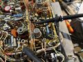
7586 used as B sweep trigger CF
-
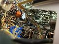
47 Ω dropper resistor for the 7586 heater.
-
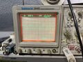
Output of the 7586 at TP836


It shall be mentioned that a complete retrofit has to be tested to not overload the ±12 V supplies.
Pictures
454
-
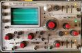
454 with traces
-

-
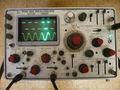
'A' intensified during 'B' mode
-
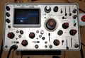
454 with P11-CRT
-
-
-

-
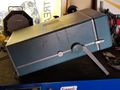
-
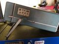
-
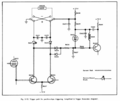
-
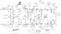
-
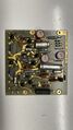
454 Voltage Regulator PCA
-
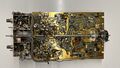
454 Vertical Amplifier component side.
-
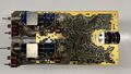
454 Vertical Amplifier soldering side with vertical sensitivity switching.
-
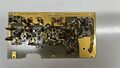
454 Vertical Output Amplifier
-
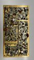
454 Trigger preamplifier, A Sweep trigger and generator PCA
-
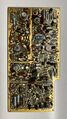
454 B Sweep delay pickoff, trigger and generator as well as horizontal amplifier PCA
-
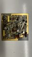
454 Z axis amplifier PCA
-
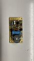
454 Calibrator PCA
-
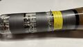
454 CRT distributed deflection assembly.


454A
-

-
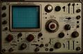
454A Front
-
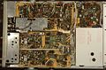
454A Bottom
-
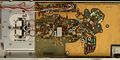
454A Vertical amp
-
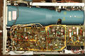
454A Top


Some Parts Used in the 454
Some Parts Used in the 454A
| Part | Part Number(s) | Class | Description | Used in |
|---|---|---|---|---|
| 154-0619-00 | 154-0619-00 | CRT | CRT | 454A |
| 155-0400-00 | 155-0400-00 | Hybrid integrated circuit | vertical amplifier | 454A |
| STD910 | 152-0310-00 | Discrete component | 5 mA, 7 pF tunnel diode | 454 • 454A |