496: Difference between revisions
No edit summary |
No edit summary |
||
| (10 intermediate revisions by 3 users not shown) | |||
| Line 1: | Line 1: | ||
{{ | {{Instrument Sidebar | ||
|class=Spectrum Analyzer | |||
summary=Spectrum Analyzer | |manufacturer=Tektronix | ||
image= Tek_496_2.jpg | | |model=496 | ||
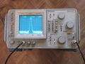
caption=Tektronix 496 | | |summary=1.8 GHz Spectrum Analyzer | ||
introduced=1982 | | |image=Tek_496_2.jpg | ||
discontinued=1989 | | |caption=Tektronix 496 | ||
manuals= | |introduced=1982 | ||
|discontinued=1989 | |||
* [[Media:070-3481-00.pdf| Tek 496 & 496P Service Manual Volume 1 | |designers= | ||
* [[Media:070-3482-00.pdf| Tek 496 & 496P Service Manual Volume 2 | |manuals= | ||
* [[Media:Tek_496_Catalog_Spec_1982.pdf| Tektronix 496 Introduction Spec ( | * [[Media:070-3480-00.pdf|Tektronix 496 and 496P Operators Manual]] | ||
* [[Media:Tek_496_Catalog_Spec_1986.pdf| Tektronix 496 Final Spec ( | * [[Media:070-3481-00.pdf|Tek 496 & 496P Service Manual Volume 1]] | ||
* [[Media:070-3482-00.pdf|Tek 496 & 496P Service Manual Volume 2]] | |||
* [[Media:070-3484-00.pdf|Tek 496P Programmers Manual]] | |||
* [[Media:Tek_496_Catalog_Spec_1982.pdf| Tektronix 496 Introduction Spec]] (OCR) | |||
* [[Media:Tek_496_Catalog_Spec_1986.pdf| Tektronix 496 Final Spec]] (OCR) | |||
}} | }} | ||
The '''Tektronix 496''' is a spectrum analyzer with a frequency range of 1 kHz to 1.8 GHz, introduced in 1982. The '''496P''' model is [[GPIB]] programmable. | |||
Non-volatile memory (NVRAM) can store up to 9 waveform displays, 10 complete front panel measurement parameter setups, and 8 K for programming macros of commonly used routines. | |||
{{BeginSpecs}} | {{BeginSpecs}} | ||
{{Spec | Frequency | {{Spec | Frequency | 1 kHz to 1.8 GHz }} | ||
{{Spec | Frequency Span | {{Spec | Frequency Span | 50 Hz to 100 MHz in 1, 2, 5 sequence (plus 0 Hz and MAX)}} | ||
{{Spec | Resolution Bandwidth | {{Spec | Resolution Bandwidth | 30 Hz; 100 Hz to 1 MHz in decade steps (-6 dB bandwidth) }} | ||
{{Spec | RF Input | {{Spec | RF Input | 50 Ω; max. +30 dBm (1 W) CW; max. 75 W peak @ 1 µs pulse, 0.1% duty factor }} | ||
{{Spec | RF Attenuator | 0 to 60 dB, 10 dB steps }} | |||
{{Spec | RF Attenuator | {{Spec | Reference Level | −123 dBm to +40 dBm }} | ||
{{Spec | Reference Level | {{Spec | Sweep Speed | 10 sec/div to 20 µs/div in 1, 2, 5 sequence }} | ||
{{Spec | Sweep Speed | {{Spec | Video Bandwidth | 0.3 Hz to 30 kHz }} | ||
{{Spec | Video Bandwidth | {{Spec | Triggering Modes | Free Run, Line, Video, Single, External }} | ||
{{Spec | Triggering Modes | Free Run, Line, Video, Single, External }} | |||
{{Spec | Displayed Average Noise | −30 dBm to −131 dBm }} | {{Spec | Displayed Average Noise | −30 dBm to −131 dBm }} | ||
{{Spec | Display Dynamic Range | 80 dB }} | {{Spec | Display Dynamic Range | 80 dB }} | ||
{{Spec | Calibrator | {{Spec | Calibrator | 50 Ω, -20 dBm ±0.3 dB at 100 MHz (Opt. 07: 75 Ω, +20 dBmV ±0.3 dB at 100 MHz) }} | ||
{{Spec | Weight | 20 kg (44 lbs) }} | |||
{{Spec | Weight | 20 kg (44 lbs) }} | {{Spec | Power | 90 − 132 V<sub>AC</sub>, 48 to 440 Hz; 180 – 250 V<sub>AC</sub>, 48 to 440 Hz, 210 W max }} | ||
{{Spec | Power | 90 − 132 V<sub>AC</sub>, 48 to 440 Hz; 180 – 250 V<sub>AC</sub>, 48 to 440 | {{Spec | Features | | ||
{{Spec | | * Continuous resolution frequency tuning | ||
* Markers provide direct readout of frequency and amplitude (single and delta) | |||
* Built-in intelligence for signal processing/marker functions | |||
* Pushbutton Occupied Bandwidth / Noise Normalization functions | |||
* Macro Capability | |||
* Optional switch-selectable 50 Ω/75 Ω Impedance | |||
* GPIB Programming | |||
}} | |||
{{EndSpecs}} | {{EndSpecs}} | ||
==Options== | ==Options== | ||
* Opt. 07: | * Opt. 07: 75 Ω dBmV input and calibration in addition to the normal 50 Ω dBm input and calibration. (Not combinable with Opt. 21 and 22; no external mixer capability). Include 42-inch 75 Ω BNC-BNC coax cable and BNC male to “F” female adapter. | ||
* Opt. 30: Rackmount with front panel input/outputs | * Opt. 30: Rackmount with front panel input/outputs | ||
* Opt. 31: Rackmount with rear panel input/output capability | * Opt. 31: Rackmount with rear panel input/output capability | ||
| Line 59: | Line 54: | ||
* Opt. 42: Replaces MARKER/VIDEO input port on the rear panel with a 110 MHz IF output port that provides a 3 dB signal bandwidth ≥ 4.5 MHz | * Opt. 42: Replaces MARKER/VIDEO input port on the rear panel with a 110 MHz IF output port that provides a 3 dB signal bandwidth ≥ 4.5 MHz | ||
Front panel inputs/outputs | |||
* RF INPUT, [[N connector]], 50 Ω; Opt. 07 adds RF INPUT 75 Ω, [[TNC connector]] | |||
* CAL OUT, [[BNC connector]] | |||
* 1ST LO OUTPUT, [[SMA connector]] (must be terminated into 50 Ω when not connected) | |||
* 2ND LO OUTPUT, [[SMA connector]] (must be terminated into 50 Ω when not connected) | |||
* Camera power | |||
Rear panel inputs/outputs: | |||
* PROBE POWER, [[LEMO S-series connector]] – ±15 V, +5 V; 100 mA max each | |||
* HORIZ/TRIG (EXT IN), [[BNC connector]] – In External Triggering mode, AC coupled input for trigger signals; When TIME/DIV selection is EXT, DC coupled input for horizontal sweep voltages. | |||
* MARKER/VIDEO (EXT IN), [[BNC connector]] – Interfaces with a Tektronix 1405 TV Adapter to display an externally-generated marker | |||
* 110 MHz IF (OUTPUT), [[BNC connector]] – Available on Opt. 42 utilizing the HORIZ (OUTPUT) connector; 110 MHz IF output with a bandwidth greater than 5 MHz | |||
* HORIZ (OUTPUT), [[BNC connector]] – 0.5 V/div horizontal signal | |||
* VERT (OUTPUT), [[BNC connector]] – Video signal, 0.5 V/Div | |||
* PEN LIFT (OUTPUT), [[BNC connector]] – TTL compatible (In Opt. 42 instruments, external video input if pin 1 of the ACCESSORIES connector is grounded) | |||
* 10 MHz IF (OUTPUT), [[BNC connector]] | |||
* EXT REF IN, [[BNC connector]] – 50 Ω input for 1, 2, 5, or 10 MHz external sinewave reference signal, –15 dBm to +15 dBm | |||
* J104 ACCESSORY (B053575 AND UP) female, [[DB25 connector]] – Bidirectional access to the instrument bus | |||
* IEEE STD 488 PORT | |||
Original included Accessories: | |||
Operator’s Manual; Operator’s Handbook; 6-ft 50Ω coaxial cable N-N; 18-inch 50Ω coaxial cable BNC-BNC; N male to BNC female adapter; rear connector shield; Power Cord; spare fuses; CRT filter set consisting of visor, blue, amber and gray light filters plus mesh filter; 496P only: Programmer Manual and GPIB cable | |||
==Links== | ==Links== | ||
* [http://www.ko4bb.com/Test_Equipment/Tek7L18-492-494_compared.php Comparison of 494] with [[492]] and [[7L18]] | * [http://www.ko4bb.com/Test_Equipment/Tek7L18-492-494_compared.php Comparison of 494] with [[492]] and [[7L18]] | ||
* [http://www.ke5fx.com/49x_notes.pdf 49x Service notes @ John Miles KE5FX] | * [http://www.ke5fx.com/49x_notes.pdf 49x Service notes @ John Miles KE5FX] | ||
* [https://www.youtube.com/watch?v=tKC24SpHTSY YouTube: Tektronix 492 and 496 Portable Spectrum Analyzers] | |||
* TekWeek 1982: [https://vintagetek.org/wp-content/uploads/2019/09/NAB_TW_04021982.pdf Tektronix taking new products to NAB] convention in Dallas, TX | |||
==Pictures== | ==Pictures== | ||
'''496P''' | |||
<gallery> | <gallery> | ||
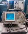
Tek_496_1.jpg | Tek_496_1.jpg | Front view | ||
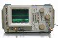
Tek_496_2.jpg | Tek_496_2.jpg | ||
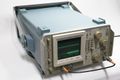
Tek_496_3.jpg | Tek_496_3.jpg | Rear view | ||
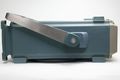
Tek_496_4.jpg | Tek_496_4.jpg | ||
Tek_496_5.jpg | Tek_496_5.jpg | Tek 496 with [[TR503]] tracking generator displaying a filter's frequency response plot | ||
Tek_496P_1.jpg | </gallery> | ||
'''496P''' | |||
<gallery> | |||
Tek_496P_1.jpg | Front view | |||
Tek_496P_2.jpg | Tek_496P_2.jpg | ||
Tek_496P_3.jpg | Tek_496P_3.jpg | ||
Tek_496P_4.jpg | Tek_496P_4.jpg | Side view | ||
</gallery> | </gallery> | ||
[[Category: Spectrum | ==Components== | ||
{{Parts|496}} | |||
[[Category:Spectrum analyzers]] | |||
Latest revision as of 07:29, 12 December 2023

The Tektronix 496 is a spectrum analyzer with a frequency range of 1 kHz to 1.8 GHz, introduced in 1982. The 496P model is GPIB programmable.
Non-volatile memory (NVRAM) can store up to 9 waveform displays, 10 complete front panel measurement parameter setups, and 8 K for programming macros of commonly used routines.
Key Specifications
| Frequency | 1 kHz to 1.8 GHz |
|---|---|
| Frequency Span | 50 Hz to 100 MHz in 1, 2, 5 sequence (plus 0 Hz and MAX) |
| Resolution Bandwidth | 30 Hz; 100 Hz to 1 MHz in decade steps (-6 dB bandwidth) |
| RF Input | 50 Ω; max. +30 dBm (1 W) CW; max. 75 W peak @ 1 µs pulse, 0.1% duty factor |
| RF Attenuator | 0 to 60 dB, 10 dB steps |
| Reference Level | −123 dBm to +40 dBm |
| Sweep Speed | 10 sec/div to 20 µs/div in 1, 2, 5 sequence |
| Video Bandwidth | 0.3 Hz to 30 kHz |
| Triggering Modes | Free Run, Line, Video, Single, External |
| Displayed Average Noise | −30 dBm to −131 dBm |
| Display Dynamic Range | 80 dB |
| Calibrator | 50 Ω, -20 dBm ±0.3 dB at 100 MHz (Opt. 07: 75 Ω, +20 dBmV ±0.3 dB at 100 MHz) |
| Weight | 20 kg (44 lbs) |
| Power | 90 − 132 VAC, 48 to 440 Hz; 180 – 250 VAC, 48 to 440 Hz, 210 W max |
| Features |
|
Options
- Opt. 07: 75 Ω dBmV input and calibration in addition to the normal 50 Ω dBm input and calibration. (Not combinable with Opt. 21 and 22; no external mixer capability). Include 42-inch 75 Ω BNC-BNC coax cable and BNC male to “F” female adapter.
- Opt. 30: Rackmount with front panel input/outputs
- Opt. 31: Rackmount with rear panel input/output capability
- Opt. 32: Benchmount. Adds side and top panels, carrying handles and feet for a stackable benchtop configuration
- Opt. 42: Replaces MARKER/VIDEO input port on the rear panel with a 110 MHz IF output port that provides a 3 dB signal bandwidth ≥ 4.5 MHz
Front panel inputs/outputs
- RF INPUT, N connector, 50 Ω; Opt. 07 adds RF INPUT 75 Ω, TNC connector
- CAL OUT, BNC connector
- 1ST LO OUTPUT, SMA connector (must be terminated into 50 Ω when not connected)
- 2ND LO OUTPUT, SMA connector (must be terminated into 50 Ω when not connected)
- Camera power
Rear panel inputs/outputs:
- PROBE POWER, LEMO S-series connector – ±15 V, +5 V; 100 mA max each
- HORIZ/TRIG (EXT IN), BNC connector – In External Triggering mode, AC coupled input for trigger signals; When TIME/DIV selection is EXT, DC coupled input for horizontal sweep voltages.
- MARKER/VIDEO (EXT IN), BNC connector – Interfaces with a Tektronix 1405 TV Adapter to display an externally-generated marker
- 110 MHz IF (OUTPUT), BNC connector – Available on Opt. 42 utilizing the HORIZ (OUTPUT) connector; 110 MHz IF output with a bandwidth greater than 5 MHz
- HORIZ (OUTPUT), BNC connector – 0.5 V/div horizontal signal
- VERT (OUTPUT), BNC connector – Video signal, 0.5 V/Div
- PEN LIFT (OUTPUT), BNC connector – TTL compatible (In Opt. 42 instruments, external video input if pin 1 of the ACCESSORIES connector is grounded)
- 10 MHz IF (OUTPUT), BNC connector
- EXT REF IN, BNC connector – 50 Ω input for 1, 2, 5, or 10 MHz external sinewave reference signal, –15 dBm to +15 dBm
- J104 ACCESSORY (B053575 AND UP) female, DB25 connector – Bidirectional access to the instrument bus
- IEEE STD 488 PORT
Original included Accessories: Operator’s Manual; Operator’s Handbook; 6-ft 50Ω coaxial cable N-N; 18-inch 50Ω coaxial cable BNC-BNC; N male to BNC female adapter; rear connector shield; Power Cord; spare fuses; CRT filter set consisting of visor, blue, amber and gray light filters plus mesh filter; 496P only: Programmer Manual and GPIB cable
Links
- Comparison of 494 with 492 and 7L18
- 49x Service notes @ John Miles KE5FX
- YouTube: Tektronix 492 and 496 Portable Spectrum Analyzers
- TekWeek 1982: Tektronix taking new products to NAB convention in Dallas, TX
Pictures
496P
-
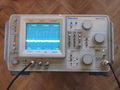
Front view
-
-
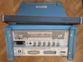
Rear view
-
-
Tek 496 with TR503 tracking generator displaying a filter's frequency response plot


496P
-
Front view
-
-

-
Side view


Components
Some Parts Used in the 496
| Part | Part Number(s) | Class | Description | Used in |
|---|---|---|---|---|
| 151-0261-00 | 151-0261-00 | Discrete component | dual PNP transistor | AM501 • AM502 • CG5001 • CG551AP • FG501 • FG502 • FG503 • OF150 • OF151 • OF152 • OF235 • OS261 • RM502A • R1140 • R5030 • R5031 • R7912 • 067-0679-00 • 067-0807-00 • 1101 • 1140A • 1141 • 1142 • 1350 • 145 • 1450 • 1480 • 1481 • 1482 • 1485 • 1501 • 1801 • 1900 • 1910 • 1980 • 213 • 26A1 • 26A2 • 2620 • 285 • 3A9 • 3A10 • 3S1 • 3S2 • 3S5 • 3S6 • 432 • 434 • 4501 • 454 • 4601 • 4602 • 4610 • 4612 • 4620 • 4632 • 4634 • 4701 • 475 • 492 • 492A • 492AP • 494 • 494P • 496 • 496P • 5A13N • 5A20N • 5A21N • 5A22N • 5A26 • 5L4N • 502A • 5030 • 5031 • 576 • 690SR • 7A22 • 7A29 • 7B51 • 7B71 • 7J20 • 7L5 • 7S11 • 7S12 • 7912AD |
| 155-0035-00 | 155-0035-00 • 155-0116-00 | Monolithic integrated circuit | quad op-amp | 3110 • 3S7 • 3T7 • 492 • 492A • 492AP • 492P • 494 • 494P • 496 • 496P • 4010 • 4011 • 4012 • 4013 • 7L5 • 7L12 • 7L13 • 7L14 • 7L18 • 7S11 • 7T11 • 7S12 • S-6 • 1461 • 4602 • P7001 • 613 • 653 |
| 155-0157-00 | 155-0157-00 | Monolithic integrated circuit | digital storage vertical control | 7L5 • 7L14 • 7L18 • 491 • 492 • 492A • 492BP • 492PGM • 494 • 494A • 495 • 496 • 497P |
| 155-0158-00 | 155-0158-00 | Monolithic integrated circuit | digital storage horizontal control | 7L5 • 7L14 • 7L18 • 491 • 492 • 492A • 492BP • 492PGM • 494 • 494A • 495 • 496 • 497P |