547: Difference between revisions
No edit summary |
Vintage dave (talk | contribs) (C808 high DF self-heats and causes HV thermal runaway) |
||
| (54 intermediate revisions by 9 users not shown) | |||
| Line 1: | Line 1: | ||
{{Oscilloscope Sidebar | | {{Oscilloscope Sidebar | ||
|manufacturer=Tektronix | |||
summary=50 MHz | |model=547 | ||
image=Tek 547 | |summary=50 MHz oscilloscope | ||
caption=Tektronix 547 with [[ | |image=Tek 547 D-Alt-Trace.jpeg | ||
introduced=1964 | | |caption=Tektronix 547 with [[1A1]] plugin, in ALT Delayed Trigger | ||
discontinued=1975 | | |introduced=1964 | ||
manuals= | |discontinued=1975 | ||
* [ | |designers=Bob Rullman;Keith Taylor;John Gates;Gene Kauffman;George Smith | ||
* [ | |series=500-series scopes | ||
* [ | |manuals= | ||
* [[Media:Tek 547 | * [[Media:070-0398-00.pdf|Tektronix 547/RM547 Manual]] <small>070-0398-00, plus "547 Notes"</small> (OCR) | ||
* [[Media:Tek_547_544_546_tech_instr_and_training.pdf|Tektronix 544/546/547 Technical Instruction and Training]] (OCR) | |||
* [[Media: | * [[Media:Tek 547 fcp.pdf|Tektronix 547 Factory Calibration Procedure]] | ||
* [[Media:Tek 547 cal procedure.pdf]] | |||
<small> | |||
'''Alternate versions''' | |||
* [https://bama.edebris.com/download/tek/547/547.djvu Tektronix 547 Manual] (DjVu @ BAMA) | |||
* [[Media:070-0398-00 (2).pdf|Tektronix 547 Manual 070-0398-00]] | |||
</small> | |||
<small> | |||
'''Modifications''' | |||
* [[Media:Tek 547 mods.pdf|Tektronix 547 Modifications]] | |||
* [[Media:050-0479-01.pdf|Disconnect Diode 547/R547 Serials 100-12479]] Tek Part [[050-0479-01]] | |||
</small> | |||
}} | }} | ||
The '''Tektronix 547''' is a 50 MHz scope that takes [[letter-series and 1-series plug-ins]]. | The '''Tektronix 547''' is a 50 MHz scope that takes [[letter-series and 1-series plug-ins]]. | ||
| Line 25: | Line 35: | ||
There is also a rackmount version, the RM547 or R547. | There is also a rackmount version, the RM547 or R547. | ||
The | The program manager for the development of the Tektronix [[544]], [[546]], and 547 was [[Bob Rullman]]. | ||
The 547 vertical amplifier was designed by [[Keith Taylor]]. | |||
{{ | {{BeginSpecs}} | ||
{{Spec | Bandwidth | DC to 50 MHz (−3 dB) with fast plug-ins ([[1A1]], [[1A2]], [[1A4]], [[1A5]]) }} | |||
{{Spec | Rise time | 7 ns with [[1A1]] }} | |||
{{Spec | Sweep Rates | 100 ns/div to 5 s/div}} | |||
{{Spec | External Horizontal Input | 100 mV/cm to 10 V/cm, DC to 400 kHz}} | |||
{{Spec | CRT | [[T5470]] (154-0478-00 standard), 10 kV acceleration, 6x10 cm viewing area }} | |||
{{Spec | Calibrator | ~1 kHz, 200 μV<sub>p-p</sub> to 100 V<sub>p-p</sub> }} | |||
{{Spec | Power | 90-136 V or 180-272 V, selected via primary voltage selector (inside cabinet) and voltage range selector (on rear panel), 50/60/400 Hz, 510 W, AC Fan }} | |||
{{EndSpecs}} | |||
==Internals== | ==Internals== | ||
===Triggering=== | ===Triggering=== | ||
The 'A' and 'B' triggers are based on a 10 mA [[tunnel diodes|tunnel diode]]. | |||
The 'A' | |||
Up to serial number 11889, it uses a [[TD253]]. | Up to serial number 11889, it uses a [[TD253]]. | ||
From 11890 onward, it uses a [[152-0140-01]]. | From 11890 onward, it uses a [[152-0140-01]]. | ||
===HV Transformer=== | ===HV Transformer=== | ||
A common problem with 547s is the [[HV transformers|HV transformer]]. | A common problem with 547s is the [[HV transformers|HV transformer]]. | ||
Rather than potting the HV transformer in wax, as was done up to that point, | Rather than potting the HV transformer in wax, as was done up to that point, the [[120-0308-00|547's HV transformer]] was potted in epoxy. | ||
the 547's HV transformer was potted in epoxy. | Unfortunately, this epoxy turned out to absorb moisture over time, particularly when used in humid climates. | ||
Unfortunately, this epoxy turned out to absorb moisture over time, | |||
particularly when used in humid climates. | |||
The moisture causes increased losses in the transformer. | The moisture causes increased losses in the transformer. | ||
Excessive losses require the regulator to drive the [[6AU5]] input oscillator tube (V800) harder. | Excessive losses require the regulator to drive the [[6AU5]] input oscillator tube (V800) harder. | ||
Eventually, the drive circuit cannot supply enough power to keep the supply in regulation. | Eventually, the drive circuit cannot supply enough power to keep the supply in regulation. | ||
The usual solution is to scavenge a replacement transformer from another scope. | The usual solution is to scavenge a replacement transformer from another scope. | ||
As a labor of love, hobbyists have been known to rebuild the HV transformers. | As a labor of love, hobbyists have been known to rebuild the HV transformers. | ||
This is discussed from time to time on the Yahoo TekScopes forum. | This is discussed from time to time on the groups.io (formerly Yahoo) TekScopes forum. | ||
Bernie Schroder has found that the HV transformer degeneration can be slowed considerably by keeping the HV module cool and dry. | |||
The mod he was taught by [[Jim Willams]] involves replacing the [[5642]] tube rectifiers with NTE517 diodes to reduce the load on the regulator circuit by about 1 Watt by eliminating the filaments. | |||
However, this can force the regulator past its design limit and result in lack of regulation, until the transformer heats up and more power is required due to losses. | |||
After changing to semiconductor diodes, it will be seen that grid pin 7 of V814 will be about 0 volts (fully on, | |||
with no swing to regulate) in an attempt to force its anode (pin 6) to about +55 V, which is the screen input of the 6AU5 (pin 8). | |||
One way to remedy this is to replace the anode resistor coming off pin 6 of V814 (R803) from 56 kΩ to 82 kΩ. | |||
Doing so changes the grid voltage on pin 7 of V814 to a comfortable −0.8 V at switch-on. | |||
Again, this becomes more negative as the losses inside the transformer increase, but not by much if the transformer is healthy. | |||
A second path to thermal runaway on early serial numbers is C808, which resonates the transformer primary winding. Tek used a Sprague 160P DiFilm Black Beauty. In the 2020's, 160P's are exhibiting high Dissipation Factor when warm, enough to self-heat in this case. Replace with any modern capacitor. | |||
===Vertical Amplifier=== | ===Vertical Amplifier=== | ||
The 547 has a five-stage BJT vertical amplifier that is fully differential from the plug-in | The 547 has a five-stage BJT vertical amplifier that is fully differential from the plug-in connector to the CRT vertical deflection plates. | ||
connector to the CRT vertical deflection plates. | There is one tube in the vertical signal path, a [[12AT7]] acting as a unity-gain buffer between the plug-in connector and the vertical amplifier. | ||
There is one tube in the vertical signal path, | |||
a [[12AT7]] acting as a unity-gain buffer between the plug-in connector and the vertical amplifier. | |||
====Spoiler Switch==== | ====Spoiler Switch==== | ||
The plug-in bay of the 547 has a "spoiler switch" that only enables the full bandwidth of the 547's | The plug-in bay of the 547 has a "spoiler switch" that only enables the full bandwidth of the 547's vertical signal path | ||
vertical signal path when certain relatively modern plug-ins are used, | when certain relatively modern plug-ins are used, such as the [[1A1]], [[1A2]], [[1A4]], and [[1A5]]. | ||
such as the [[1A1]], [[1A2]], [[1A4 | |||
Those plug-ins have a small hole to the left of the plug-in to mainframe connector, | Those plug-ins have a small hole to the left of the plug-in to mainframe connector, so they can be fully inserted without pressing the spoiler switch. | ||
so they can be fully inserted without pressing the spoiler switch. | (Spectrum analyzer plug-in Types [[1L30]] and [[1L40]] have the hole too but for no reason since their vertical output is low frequency.) | ||
* [[Media:Spoiler switch rationale from Tek 547 544 546 tech instr and training.pdf|Spoiler switch explanation excerpted from Tek 547 544 546 Technical Instruction and Training]] | |||
* [[Media:Spoiler switch rationale from Tek 547 notes.pdf|Spoiler switch explanation excerpted from Tek 547 Notes]] | |||
====Delay Line==== | ====Delay Line==== | ||
| Line 70: | Line 99: | ||
===Power Supply === | ===Power Supply === | ||
The 547's power supply provides regulated outputs of −150 V, +100 V, +225 V, +350 V, | The 547's power supply provides regulated outputs of −150 V, +100 V, +225 V, and +350 V, plus a +325 V unregulated output for the CRT HV oscillator. | ||
Multiple secondary windings | Multiple secondary windings feed diodes for rectification for different voltages, using both center-tap and bridge configurations. | ||
The regulator section uses no transistors, only tubes. There are multiple 6.3 V secondary outputs for heaters, some elevated to different voltage levels | |||
There are multiple 6. | based on the section/tube that is supplied, in order to keep the heater-to-cathode voltage level within limits. | ||
As is common in many Tektronix scopes, | As is common in many Tektronix scopes, all regulated voltages are referred to the negative regulated rail (−150 V in this case) by fixed low-tolerance dividers. | ||
all regulated voltages are referred to the negative regulated rail (−150 V in this case) by fixed low-tolerance dividers. | Only the −150 V voltage is trimmed; its reference is a [[OG3]] VR tube. | ||
Only the −150 V voltage is trimmed | |||
A [[12AX7]] is used as the comparator and two [[6CW5]] in parallel are used as series pass tubes. | A [[12AX7]] is used as the comparator and two [[6CW5]] in parallel are used as series pass tubes. | ||
A [[6AU6]] is used as an error amplifier. | A [[6AU6]] is used as an error amplifier. | ||
Most other power supply sections in the 547 replicate the same basic design, | Most other power supply sections in the 547 replicate the same basic design, except slight changes in tubes used: | ||
except slight changes in tubes used | The +225 V and +100 V regulators employ a [[6080]] as the pass element, and +350 uses a [[6CW5]]. | ||
The plate voltage delay circuit is similar to that found in many may other | The plate voltage delay circuit is similar to that found in many may other Tek scopes of the same era. | ||
Heater voltage is applied to all tubes immediately when the power switch is turned on. | Heater voltage is applied to all tubes immediately when the power switch is turned on. | ||
A [[6N030T|6N030T delay tube (P/N 148-0021-00)]] controls a relay that switches plate supply voltages on only after the tubes are warmed up. | |||
==Links== | ==Links== | ||
| Line 100: | Line 126: | ||
* [http://www.ebay.com/gds/The-Tektronix-547-Oscilloscope-Magic-in-the-Box-/10000000000725321/g.html The Tektronix 547 Oscilloscope - Magic in the Box] | * [http://www.ebay.com/gds/The-Tektronix-547-Oscilloscope-Magic-in-the-Box-/10000000000725321/g.html The Tektronix 547 Oscilloscope - Magic in the Box] | ||
* [http://www.thevalvepage.com/testeq/tek/547/547.htm J.Evans's 547 page] | * [http://www.thevalvepage.com/testeq/tek/547/547.htm J.Evans's 547 page] | ||
==Common Problems== | |||
* See [[547/Repairs]] | |||
==Pictures== | ==Pictures== | ||
===547=== | |||
<gallery> | <gallery> | ||
Tek 547 1a2 new.jpg | Tek 547 trace.jpg | 547 with [[1A2]] | ||
Tek 547 1a2 new.jpg|547 with [[1A2]] | |||
Tek 547.jpg|Front view | Tek 547.jpg|Front view | ||
Tek 547 eng.jpg|547 serial "ENG B 23" | |||
Tek 547 eng2.jpg|547 serial "ENG B 23" | |||
Tek | |||
Tek | |||
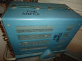
Tek 547 ampex front.jpg | Tek 547 ampex front.jpg | ||
Tek 547 | Tek_547_Delayed_Trigger1.JPG | Tek 547 Delayed Trigger & ALT Sweep | ||
Tek 547 | Tek_547_Delayed_Trigger2.jpg | Tek 547 Delayed Trigger & ALT Sweep | ||
Tek 547 trace two sine.jpg|547 trace | |||
Tek 547 1a1 front.jpg|547 with [[1A1]] | |||
Tek_547_4-Trace.jpg | 547 with 1A2 in ALT Sweep Mode | |||
Tek_547_Delayed_Trig.jpg | 547 Delayed Trace | |||
Tek 547 ampex right external.jpg | Tek 547 ampex right external.jpg | ||
Tek 547 ampex rear.jpg | Tek 547 ampex rear.jpg | ||
Grey face 547.jpg|Gray 547 | Grey face 547.jpg|Gray 547 | ||
Tek 547 rear close.jpg | Tek 547 rear close.jpg | ||
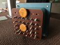
Tek 547 rear connections.jpg|rear connections | Tek 547 rear connections.jpg|rear connections | ||
Tek_547_Vert_Amp.jpg | Tek 547 Vertical Amplifier | </gallery> | ||
===547 Internals=== | |||
<gallery> | |||
Tek_547-Top.jpeg | Internals - Top | |||
Tek_547-RHS-TBOpen.jpeg | Internals - RHS | |||
Tek_547-RHS.jpeg | Internals - Time Base - RHS | |||
Tek_547-Internal-LHS.jpeg | Internals - LHS | |||
Tek_547-Internal-Bottom.jpeg | Internals - Bottom | |||
Tek_547_HVSection-NoCover.jpg | Tek 547 HV Section and [[5642]]HV Rectifier Tube (Cover removed) | |||
Tek_547_HV_Diodes.jpg | Solid State HV Diode Mod | |||
Tek_547-TunnelDiodes-Trigger.jpg | Tunnel Diodes TD253 and TD3A in a Tek 547 Trigger/ Sweep Section | |||
Tunnel_DIode_1D2_2.2mA.jpg | 2.2 mA Tunnel Diode in 547 Delay Pickoff | |||
Tek_547_Vert_Amp.jpg | Tek 547 Vertical Amplifier. The output transistors are mounted on [[beryllium oxide]] discs. | |||
547_01.JPG|Top | |||
547_02.JPG|Right | |||
547_03.JPG|Left | |||
Tek_547_CRT1.jpg | Tek 547 CRT | Tek_547_CRT1.jpg | Tek 547 CRT | ||
Tek_547_CRT2.jpg | Tek 547 CRT Side View | Tek_547_CRT2.jpg | Tek 547 CRT Side View | ||
Tek_547_CRT_Def_Plates1.jpg | Tek 547 CRT Deflection Plates & Assembly | Tek_547_CRT_Def_Plates1.jpg | Tek 547 CRT Deflection Plates & Assembly | ||
Tek_547_CRT_Def_Plates2.jpg | Tek 547 CRT Electron Gun Assembly | Tek_547_CRT_Def_Plates2.jpg | Tek 547 CRT Electron Gun Assembly | ||
Tek_547_Chassis_Without_CRT.jpg | Tek 547 Chassis Without CRT and Plug in | Tek_547_Chassis_Without_CRT.jpg | Tek 547 Chassis Without CRT and Plug in | ||
Tek_547_Screen.jpg | Tek 547 Screen Scale | Tek_547_Screen.jpg | Tek 547 Screen Scale | ||
Tek_547_Power-Transformer3.jpg | Tek 547 Main Transformer | Tek_547_Power-Transformer3.jpg | Tek 547 Main Transformer | ||
Tek_547_Power-Transformer2.jpg | Tek 547 Main Transformer | Tek_547_Power-Transformer2.jpg | Tek 547 Main Transformer | ||
Tek_547_Power-Transformer1.jpg | Tek 547 Main Transformer | Tek_547_Power-Transformer1.jpg | Tek 547 Main Transformer | ||
Tek_547_Tubes.jpg | Tek 547 Inside view with Power ON | Tek_547_Tubes.jpg | Tek 547 Inside view with Power ON | ||
Tek_547_Transformer.jpg | 547 LV Transformer Connections | Tek_547_Transformer.jpg | 547 LV Transformer Connections | ||
Tek_547_Inside_Tubes.jpg | Inside a Tek 547 | Tek_547_Inside_Tubes.jpg | Inside a Tek 547 | ||
Tek 547 ampex right internal.jpg | |||
Tek 547 ampex left internal.jpg | |||
Tek 547 | </gallery> | ||
=== RM 547=== | |||
<gallery> | |||
Tek rm547.jpg|RM547 | |||
Tek rm547 trace.jpg | |||
Tektronix rm547.jpg | |||
</gallery> | |||
=== Schematics === | |||
<gallery> | |||
Tek-547-trigger a.png|Trigger A | |||
Tek-547 vert amp2.png|Vertical amplifier | |||
</gallery> | </gallery> | ||
==Components== | |||
{{Parts|547}} | |||
[[Category:500 series scopes]] | [[Category:500 series scopes]] | ||
Latest revision as of 18:48, 2 February 2024

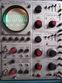
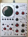
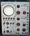
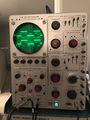
The Tektronix 547 is a 50 MHz scope that takes letter-series and 1-series plug-ins.
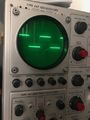
It has two identical timebases and, when used with the 1A1, 1A2, or 1A4, has the ability to display one input with one time scale and another input with a different time scale. The effect is similar to a dual-beam scope assuming that the input signals are repetitive. This "Sweep Switching" feature differentiates the 547 from the 546.
There is also a rackmount version, the RM547 or R547.
The program manager for the development of the Tektronix 544, 546, and 547 was Bob Rullman. The 547 vertical amplifier was designed by Keith Taylor.
Key Specifications
| Bandwidth | DC to 50 MHz (−3 dB) with fast plug-ins (1A1, 1A2, 1A4, 1A5) |
|---|---|
| Rise time | 7 ns with 1A1 |
| Sweep Rates | 100 ns/div to 5 s/div |
| External Horizontal Input | 100 mV/cm to 10 V/cm, DC to 400 kHz |
| CRT | T5470 (154-0478-00 standard), 10 kV acceleration, 6x10 cm viewing area |
| Calibrator | ~1 kHz, 200 μVp-p to 100 Vp-p |
| Power | 90-136 V or 180-272 V, selected via primary voltage selector (inside cabinet) and voltage range selector (on rear panel), 50/60/400 Hz, 510 W, AC Fan |
Internals
Triggering
The 'A' and 'B' triggers are based on a 10 mA tunnel diode. Up to serial number 11889, it uses a TD253. From 11890 onward, it uses a 152-0140-01.
HV Transformer
A common problem with 547s is the HV transformer. Rather than potting the HV transformer in wax, as was done up to that point, the 547's HV transformer was potted in epoxy. Unfortunately, this epoxy turned out to absorb moisture over time, particularly when used in humid climates. The moisture causes increased losses in the transformer.
Excessive losses require the regulator to drive the 6AU5 input oscillator tube (V800) harder. Eventually, the drive circuit cannot supply enough power to keep the supply in regulation. The usual solution is to scavenge a replacement transformer from another scope. As a labor of love, hobbyists have been known to rebuild the HV transformers. This is discussed from time to time on the groups.io (formerly Yahoo) TekScopes forum.
Bernie Schroder has found that the HV transformer degeneration can be slowed considerably by keeping the HV module cool and dry. The mod he was taught by Jim Willams involves replacing the 5642 tube rectifiers with NTE517 diodes to reduce the load on the regulator circuit by about 1 Watt by eliminating the filaments. However, this can force the regulator past its design limit and result in lack of regulation, until the transformer heats up and more power is required due to losses.
After changing to semiconductor diodes, it will be seen that grid pin 7 of V814 will be about 0 volts (fully on, with no swing to regulate) in an attempt to force its anode (pin 6) to about +55 V, which is the screen input of the 6AU5 (pin 8).
One way to remedy this is to replace the anode resistor coming off pin 6 of V814 (R803) from 56 kΩ to 82 kΩ. Doing so changes the grid voltage on pin 7 of V814 to a comfortable −0.8 V at switch-on.
Again, this becomes more negative as the losses inside the transformer increase, but not by much if the transformer is healthy.
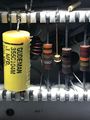
A second path to thermal runaway on early serial numbers is C808, which resonates the transformer primary winding. Tek used a Sprague 160P DiFilm Black Beauty. In the 2020's, 160P's are exhibiting high Dissipation Factor when warm, enough to self-heat in this case. Replace with any modern capacitor.
Vertical Amplifier
The 547 has a five-stage BJT vertical amplifier that is fully differential from the plug-in connector to the CRT vertical deflection plates. There is one tube in the vertical signal path, a 12AT7 acting as a unity-gain buffer between the plug-in connector and the vertical amplifier.
Spoiler Switch
The plug-in bay of the 547 has a "spoiler switch" that only enables the full bandwidth of the 547's vertical signal path when certain relatively modern plug-ins are used, such as the 1A1, 1A2, 1A4, and 1A5.
Those plug-ins have a small hole to the left of the plug-in to mainframe connector, so they can be fully inserted without pressing the spoiler switch. (Spectrum analyzer plug-in Types 1L30 and 1L40 have the hole too but for no reason since their vertical output is low frequency.)
- Spoiler switch explanation excerpted from Tek 547 544 546 Technical Instruction and Training
- Spoiler switch explanation excerpted from Tek 547 Notes
Delay Line
There is a 170 nanosecond delay line between the first and second gain stages.
Power Supply
The 547's power supply provides regulated outputs of −150 V, +100 V, +225 V, and +350 V, plus a +325 V unregulated output for the CRT HV oscillator.
Multiple secondary windings feed diodes for rectification for different voltages, using both center-tap and bridge configurations. The regulator section uses no transistors, only tubes. There are multiple 6.3 V secondary outputs for heaters, some elevated to different voltage levels based on the section/tube that is supplied, in order to keep the heater-to-cathode voltage level within limits.
As is common in many Tektronix scopes, all regulated voltages are referred to the negative regulated rail (−150 V in this case) by fixed low-tolerance dividers. Only the −150 V voltage is trimmed; its reference is a OG3 VR tube. A 12AX7 is used as the comparator and two 6CW5 in parallel are used as series pass tubes. A 6AU6 is used as an error amplifier. Most other power supply sections in the 547 replicate the same basic design, except slight changes in tubes used: The +225 V and +100 V regulators employ a 6080 as the pass element, and +350 uses a 6CW5.
The plate voltage delay circuit is similar to that found in many may other Tek scopes of the same era. Heater voltage is applied to all tubes immediately when the power switch is turned on. A 6N030T delay tube (P/N 148-0021-00) controls a relay that switches plate supply voltages on only after the tubes are warmed up.
Links
- 547 Restoration with video
- Tek 547 in "Reading Jim Williams" blog: Scope Sunday 13 and Vintage Scopes are Better, pt.1
- "MightyOhm" blog: Jim Williams workbench
- Comparing an Apollo Era Workhorse to Today’s Bench Scope @ tek.com
- Eiki Martinson: Tektronix 547 Oscilloscope—Getting an Old Soldier Back in the Fight
- Tek 547 page @ amplifier.cd
- The Tektronix 547 Oscilloscope - Magic in the Box
- J.Evans's 547 page
Common Problems
- See 547/Repairs
Pictures
547
-
547 with 1A2
-
547 with 1A2
-

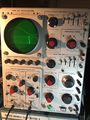
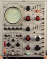
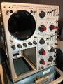
Front view
-
547 serial "ENG B 23"
-
547 serial "ENG B 23"
-

-
Tek 547 Delayed Trigger & ALT Sweep
-
Tek 547 Delayed Trigger & ALT Sweep
-
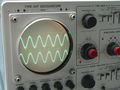
547 trace
-
547 with 1A1
-
547 with 1A2 in ALT Sweep Mode
-
547 Delayed Trace
-
-

-
Gray 547
-

-
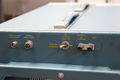
rear connections


547 Internals
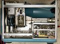
-
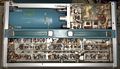
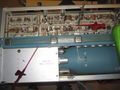
Internals - Top
-
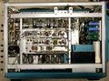
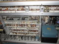
Internals - RHS
-
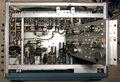
Internals - Time Base - RHS
-
Internals - LHS
-

Internals - Bottom
-
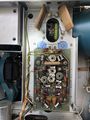
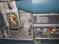
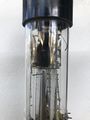
Tek 547 HV Section and 5642HV Rectifier Tube (Cover removed)
-
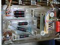
Solid State HV Diode Mod
-
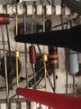
Tunnel Diodes TD253 and TD3A in a Tek 547 Trigger/ Sweep Section
-
2.2 mA Tunnel Diode in 547 Delay Pickoff
-
Tek 547 Vertical Amplifier. The output transistors are mounted on beryllium oxide discs.
-
Top
-
Right
-
Left
-
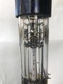
Tek 547 CRT
-
Tek 547 CRT Side View
-
Tek 547 CRT Deflection Plates & Assembly
-
Tek 547 CRT Electron Gun Assembly
-
Tek 547 Chassis Without CRT and Plug in
-
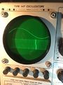
Tek 547 Screen Scale
-
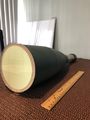
Tek 547 Main Transformer
-
Tek 547 Main Transformer
-
Tek 547 Main Transformer
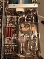
-
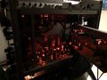
Tek 547 Inside view with Power ON
-
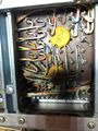
547 LV Transformer Connections
-
Inside a Tek 547
-

-


RM 547
-
RM547
-

-


Schematics
-
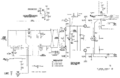
Trigger A
-
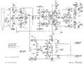
Vertical amplifier


Components
Some Parts Used in the 547
| Part | Part Number(s) | Class | Description | Used in |
|---|---|---|---|---|
| 0G3 | 154-0291-00 | Gas Discharge Tube (Voltage regulator) | 85 V voltage reference | 132 • 506 • 547 • 560 • 561 • 561A • 561S • 564 • 565 • 567 • 661 • TU-4 • Z |
| 120-0308-00 | 120-0308-00 | Discrete component | high voltage transformer | 543B • 544 • 545B • 546 • 547 |
| 12AT7 | 154-0039-00 | Vacuum Tube (Dual Triode) | dual high-gain triode | 161 • 180 • 310 • 310A • 315 • 316 • 360 • 502 • 502A • 511A • 512 • 513 • 513D • 514 • 514AD • 514D • 516 • 524 • 529 • RM529 • 544 • 546 • 547 • 556 • 565 • 570 • 3A2 • 75 • 3A75 • 1M1 • A • B • C • G • H • K • L • ML • M • N • K • R • S • Z |
| 12AU6 | 154-0040-00 | Vacuum Tube (Pentode) | RF pentode | 81 • 112 • 1L10 • 1L20 • 1L60 • 3L10 • 512 • 556 • 575 • 545 • 547 • 549 • 581 • 585 • A • B • C • G • K • H • L • ML • M • N • O • R • S • Z |
| 12AU7 | 154-041 • 154-0041-00 • 154-0287-00 | Vacuum Tube (Dual Triode) | dual medium-μ triode | 104 • 104A • 122 • 160 • 161 • 162 • 181 • 190 • 310 • 310A • 316 • 317 • 3C66 • 502 • 502A • 507 • 511A • 512 • 516 • 517 • 517A • 524 • 526 • 535 • 536 • 545 • 545A • 545B • 547 • 549 • 555 • 561 • 564 • 570 • 575 • 581 • 581A • 585 • 585A • C • D • E • N • Q • Hickok 1825 |
| 12AX7 | 154-043 • 154-0043-00 | Vacuum Tube (Dual Triode) | dual triode | 3C66 • 513 • 524 • 531 • 531A • 535 • 536 • 545 • 545A • 545B • 546 • 547 • 549 • 555 • 570 • 581 • 581A • 585 • 585A • E • Q • Hickok 1825 |
| 12B4 | 154-044 • 154-0044-00 | Vacuum Tube (Triode) | power triode | 126 • 310 • 310A • 316 • 317 • 502 • 502A • 524 • 526 • 541 • 541A • 535 • 535A • 545 • 545A • 546 • 547 • 570 • 549 • 551 • 555 • 513 • 581 • 581A • 585 • 585A |
| 1N3714 | 152-0081-00 | Discrete component | 2.2 mA, 25 pF germanium tunnel diode | 546 • 547 • 556 • 21A • 22A • 3B1 • 3B2 • 3B3 • 422 • 491 • 283 |
| 1N3717 | 152-0381-00 • 152-0125-00 | Discrete component | 4.7 mA, 25 pF tunnel diode | 1L40 • 1S1 • 1S2 • 11B1 • 11B2 • 11B2A • 147A • 1470 • 148 • 21A • 22A • 3B4 • 3B5 • 408 • 432 • 434 • 453 • 453A • 454 • 466 • 491 • 5T3 • 544 • RM544 • 546 • RM546 • 547 • RM547 • 556 • RM556 • 7B70 • 7B71 • 7D11 |
| 2N2207 | 151-063 • 151-0063-00 | Discrete component | germanium PNP transistor | 3B1 • 3B3 • 3S76 • 321A • 547 |
| 5642 | 154-0051-00 • 154-0079-00 | Vacuum Tube (Diode) | directly-heated high-voltage rectifier | 310 • 310A • 316 • 317 • 360 • 453 • 502 • 502A • 503 • 504 • 506 • 513 • 515 • 516 • 524 • 529 • RM529 • 533 • 533A • 535 • 536 • 543 • 543A • 543B • 545 • 545A • 545B • 547 • 551 • 555 • 556 • 560 • 561 • 561A • 561S • 564 • 567 • 570 • 575 • 581 • 581A • 585 • 585A • 647 • 647A |
| 6080 | 154-0056-00 • 154-0315-00 | Vacuum Tube (Dual Triode) | dual power triode | 132 • 160 • 316 • 317 • 516 • 535 • 535A • RM35A • 541 • 541A • 535 • 536 • 545 • 545A • 545B • 546 • 547 • 549 • 565 • 567 • 575 • 581 • 581A • 585 • 585A |
| 6197 | 154-0146-00 | Vacuum Tube (Pentode) | 7.5 W power pentode | 516 • 531 • 533 • 535 • 535A • 547 • 556 • 75 • 3A75 |
| 6AU5 | 154-021 • 154-0021-00 | Vacuum Tube (Pentode) | 10 W beam power pentode | 507 • 513 • 516 • 517 • 517A • 531 • 535 • 541 • 535 • 545 • 547 • 581 • 581A • 585 • 585A |
| 6AU6 | 154-0022-00 • 157-0073-00 • 157-0059-00 • 154-0284-00 | Vacuum Tube (Pentode) | RF pentode | 107 • 160 • 181 • 190 • 60 • 2A60 • 72 • 3A72 • 3C66 • 310 • 310A • 316 • 317 • 360 • 502 • 502A • 506 • 511 • 511A • 512 • 513 • 516 • 517 • 517A • 524 • 526 • 529 • RM529 • 531 • 531A • 535 • 536 • 545 • 545A • 546 • 547 • 549 • 555 • 561 • 561A • 561S • 564 • 565 • 567 • 570 • 575 • 581 • 581A • 585 • 585A • 80 • C • CA • Q |
| 6BY8 | 154-0414-00 | Vacuum Tube (Pentode) | diode-pentode | 547 |
| 6CW5 | 154-0202-00 | Vacuum Tube (Pentode) | power pentode | 132 • 526 • 547 • General Radio 1124 • Telequipment D56 |
| 6DJ8 | 154-0187-00 • 154-0305-00 | Vacuum Tube (Dual Triode) | dual triode | 132 • 161 • 310A • 316 • 317 • 502 • 502A • 503 • 504 • 506 • 515 • 516 • 519 • 526 • 529 • RM529 • 533 • 535 • 536 • 543 • 544 • 545 • 545A • 545B • 546 • 547 • 549 • 555 • 556 • 561A • 561S • 564 • 565 • 567 • 581 • 581A • 585 • 585A • 661 • 1A4 • 1S1 • 60 • 2A60 • 63 • 2A63 • 67 • 2B67 • 3A1 • 3A1S • 3A2 • 3A3 • 3A6 • 3A7 • 72 • 3A72 • 75 • 3A75 • 4S2 • 51 • 3B1 • 3B1S • 3B2 • 3B3 • 3B4 • 3M1 • 3S76 • 3T77 • 3T77A • 9A1 • 9A2 • 1121 • 80 • 81 • 82 • 86 • B • O • W • Z • Telequipment D56 • Telequipment S32A • Telequipment D52 • S-311 • Telequipment TD51 • Telequipment S52 • Telequipment S51 • Telequipment Type A • TU-4 |
| 8426 | Vacuum Tube (Pentode) | RF pentode | O • 545A • 547 • 549 • 581A • 585A | |
| SMTD995 | 152-0140-01 | Discrete component | 10 mA, 8 pF tunnel diode | 1S1 • 1S2 • 1502 • 21A • 22A • 3T5 • 3T6 • 475 • 475A • 475M • 544 • R544 • 546 • RM546 • 547 • RM547 • 556 • R556 • 581A • 585A • RM585 • 7B52 • 7B53N • 7B70 • 7B71 • 7D10 • 7D11 • 7T11 • 7T11A • R7912 • S-51 • S-52 • TU-5 • 067-0572-00 • 067-0572-01 • 067-0681-00 |
| STD704 | 152-0125-00 | Discrete component | 4.7 mA tunnel diode | 1L40 • 1S1 • 11B1 • 11B2 • 11B2A • 147 • R147 • 147A • R147A • 1470 • 148 • R148 • 148-M • 149 • R149 • 149A • R149A • 21A • 22A • 3B4 • 3B5 • 408 • 432 • 434 • 453 • 453A • 454 • 464 • 465 • 466 • 491 • 5T3 • 544 • RM544 • 546 • RM546 • 547 • RM547 • 556 • RM556 • 7B70 • 7B71 • 7D11 |
| T5470 | 154-0429-00 • 154-0450-00 • 154-0451-00 • 154-0452-00 • 154-0457-00 • 154-0458-00 • 154-0459-00 • 154-0478-00 • 154-0478-01 • 154-0478-02 • 154-0478-03 • 154-0568-00 • 154-0568-01 • 154-0568-02 • 154-0568-03 | CRT | 5" electrostatic deflection CRT | 543B • 544 • 545B • 546 • 547 |
| TD202 | 152-0155-00 | Discrete component | 2.2 mA, 25 pF tunnel diode | 546 • RM546 • 547 • RM547 |
| TD253 | 152-0154-00 | Discrete component | 10 mA, 9 pF germanium tunnel diode | 547 • 7B70 |
| TD714 | 152-0402-00 | Discrete component | 2.2 mA, 25 pF tunnel diode | 1401 • 1401A • 283 • R283 • 3B2 • 3B3 • 422 • 491 • 546 • RM546 • 547 • RM547 • 556 • RM556 • SPG11 • SPG12 |