S-50: Difference between revisions
No edit summary |
No edit summary |
||
| Line 78: | Line 78: | ||
| snap-off diode capacitively coupled to TD, like in [[284]] | | snap-off diode capacitively coupled to TD, like in [[284]] | ||
|} | |} | ||
==Links== | |||
{{Documents|Link=S-50}} | |||
{{PatentLinks|S-50}} | |||
==Pictures== | ==Pictures== | ||
Latest revision as of 10:51, 19 June 2024
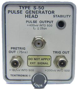
The Tektronix S-50 is a pulse generator head that produces 400 mV pulses with a rise time under 25 ps. The pulse output is an SMA connector. The PRETRIG OUT and TRIG OUT signals use BSM connectors.
The output diode is the same one that the S-52 uses, the 153-0040-00. The internal timing circuitry of the S-50 uses two 152-0379-00 tunnel diodes.
Comparison of S-50 and S-52
The S-50 is similar to the S-52, but the output pulse amplitude of the S-50 is 400 mV, twice that of the S-52. The S-50's output tunnel diode is directly connected to the main pulse output connector. The S-52 has a 48-ohm resistor between the output tunnel diode and the main pulse output connector, resulting in a 2:1 voltage divider. Another difference between the S-50 and S-52 is the presence of a TRIG OUT on the front of the of S-50. Both have PRETRIGGER OUT connectors. The pretrigger of the S-50 leads the main pulse by 75 ns, that of the S-52 by 85 ns.
At the circuit level, the S-50 and S-52 differ significantly. Both use a current switch to bias the output tunnel diode when it is in the "armed" state. The S-50 uses another tunnel diode to add a short pulse of current that "fires" the output tunnel diode. The S-52 uses a snap-off diode to generate this firing pulse.
Sequencing of events (arming the output diode, firing it, resetting it) is controlled by analog timing circuits in the S-50. The S-52 uses a digital counter and a decoder to generate the internal control signals.
Specifications
S-50 S-52 Risetime under 25 ps under 25 ps Amplitude 400 mV into 50 Ω 200 mV into 50 Ω Output impedance varies, not specified 50 Ω Sequencing of internal events analog timing circuit digital state-machine Pretrigger lead time 75 ns 85 ns Pretrigger to pulse jitter 15 ps 10 ps Pulse repetition rate 25 kHz 120 kHz Trigger (with pulse) output yes, 200 mV into 50 Ω no Output TD tripper scheme current pulse through TD bias transistor snap-off diode capacitively coupled to TD, like in 284
Links
Documents Referencing S-50
| Document | Class | Title | Authors | Year | Links |
|---|---|---|---|---|---|
| Service Scope 52 Oct 1968.pdf | Article | The State of the Art in Sampling | Al Zimmerman | 1968 | S-1 • S-2 • S-3 • S-4 • S-50 • S-51 • 285 • 3S1 • 3S2 • 3S5 • 3S6 • 3T2 • 3T5 • 3T6 • 3T77A • 568 • 230 |
Pictures
-
block diagram
-
schematic
-
front view
-
-
-
left internal view
-
right internal view


