11201: Difference between revisions
No edit summary |
No edit summary |
||
| (19 intermediate revisions by 3 users not shown) | |||
| Line 6: | Line 6: | ||
|image=Tek 11201.JPG | |image=Tek 11201.JPG | ||
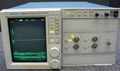
|caption=Tek 11201 | |caption=Tek 11201 | ||
|introduced= | |introduced=1989 | ||
|discontinued=1990 | |discontinued=1990 | ||
|designers= | |designers= | ||
| Line 13: | Line 13: | ||
* [[Media:Tek 11201 1989 catalog.pdf|Tektronix 11201 Description in 1989 Catalog]] | * [[Media:Tek 11201 1989 catalog.pdf|Tektronix 11201 Description in 1989 Catalog]] | ||
* [[Media:Tek 11201 sales.pdf|Tektronix 11201 Product Annoucement]] | * [[Media:Tek 11201 sales.pdf|Tektronix 11201 Product Annoucement]] | ||
{{ROM Images}} | |||
* 160-5973-01 | |||
* 160-5974-01 | |||
}} | }} | ||
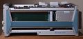
The '''Tektronix 11201''' is a 400 MHz sampling oscilloscope. It does not take plug-ins | The '''Tektronix 11201''' is a 400 MHz sampling oscilloscope. It does not take plug-ins, | ||
but it is electrically similar to the [[11401]] with two 11A32 plugins and uses the same firmware. | |||
The 11201 is specified to have nine bits of vertical resolution whereas the 11401 and 11402 are specified to have ten bits of vertical resolution. | |||
[[ | [[David White]] was the project manager for the 11201. | ||
{{MissingSpecs}} | |||
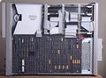
==Internals== | |||
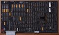
The 11201 has a card cage containing five boards: | |||
# I/O Board (A14) | |||
# Memory Management Unit Board (A15) | |||
# Compressor Board (A16) | |||
# Main Processor Board (A17) | |||
# Memory Board (A18) | |||
The five boards plug into the card cage interconnect, which is completely passive. | |||
All card cage interconnects are 96-pin DIN 41612 connectors (3 rows of 32 pins each, also used for VME bus) that are wired identically. | |||
The main microprocessor for the 11201 is an [[Intel 80286]] with an 80287 math co-processor. | |||
==Pictures== | ==Pictures== | ||
| Line 29: | Line 45: | ||
Tek 11201a twotrace.jpg | Tek 11201a twotrace.jpg | ||
Tek 11201a rear.jpg | Tek 11201a rear.jpg | ||
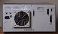
Tek 11201 front powered off.jpeg|Front, powered off | |||
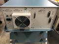
Tek 11201 rear.jpeg|Rear | |||
</gallery> | </gallery> | ||
'''Displays''' | |||
<gallery> | |||
Tek 11201 trace.jpeg|Trace | |||
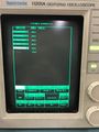
Tek 11201 instrument options screen.jpeg|Instrument Options Screen | |||
</gallery> | |||
'''Internal''' | |||
<gallery> | |||
Tek 11201 bottom internal.jpeg|11201 Bottom internal | |||
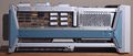
Tek 11201 top internal.jpeg|11201 Top internal | |||
Tek 11201 left internal.jpeg|11201 Left internal | |||
Tek 11201 right internal.jpeg|Right internal | |||
</gallery> | |||
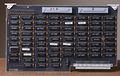
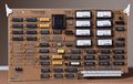
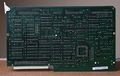
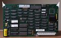
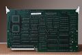
'''Boards''' | |||
<gallery> | |||
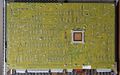
Tek 11201 acquisition board component side.jpeg|11201 Acquisition Board | |||
Tek 11201 waveform compressor component side.jpeg|Waveform Compressor Board | |||
Tek 11201 waveform compressor solder side.jpeg|Waveform Compressor Board | |||
Tek 11201 memory management board component side.jpeg|Memory Management Board | |||
Tek 11201 memory management board solder side.jpeg|Memory Management Board | |||
Tek 11201 memory board component side.jpeg|Memory Board | |||
Tek 11201 memory board solder side.jpeg|Memory Board | |||
Tek 11201 io board component side.jpeg|I/O Board | |||
Tek 11201 io board solder side.jpeg|I/O Board | |||
Tek 11201 processor board component side.jpeg|Processor Board | |||
Tek 11201 processor board solder side.jpeg|Processor Board | |||
Tek 11201 acquisition board solder side.jpeg|Acquisition Board | |||
Tek 11201 timebase board component side.jpeg|Timebase Board | |||
Tek 11201 display controller component side.jpeg|Display Controller | |||
Tek 11201 display controller solder side.jpeg|Display Controller | |||
</gallery> | |||
==Components== | |||
{{Parts|11201}} | |||
[[Category:11000 series mainframes]] | [[Category:11000 series mainframes]] | ||
Latest revision as of 06:48, 3 July 2024

The Tektronix 11201 is a 400 MHz sampling oscilloscope. It does not take plug-ins, but it is electrically similar to the 11401 with two 11A32 plugins and uses the same firmware.
The 11201 is specified to have nine bits of vertical resolution whereas the 11401 and 11402 are specified to have ten bits of vertical resolution.
David White was the project manager for the 11201.
Key Specifications
- please add
Internals
The 11201 has a card cage containing five boards:
- I/O Board (A14)
- Memory Management Unit Board (A15)
- Compressor Board (A16)
- Main Processor Board (A17)
- Memory Board (A18)
The five boards plug into the card cage interconnect, which is completely passive. All card cage interconnects are 96-pin DIN 41612 connectors (3 rows of 32 pins each, also used for VME bus) that are wired identically.
The main microprocessor for the 11201 is an Intel 80286 with an 80287 math co-processor.
Pictures
-
-

-
-

-
-

Front, powered off
-
Rear


Displays
-
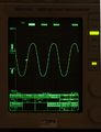
Trace
-
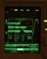
Instrument Options Screen


Internal
-

11201 Bottom internal
-
11201 Top internal
-
11201 Left internal
-
Right internal


Boards
-

11201 Acquisition Board
-
Waveform Compressor Board
-
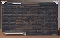
Waveform Compressor Board
-
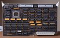
Memory Management Board
-

Memory Management Board
-
Memory Board
-

Memory Board
-

I/O Board
-
I/O Board
-
Processor Board
-
Processor Board
-
Acquisition Board
-

Timebase Board
-
Display Controller
-

Display Controller


Components
Some Parts Used in the 11201
| Part | Part Number(s) | Class | Description | Used in |
|---|---|---|---|---|
| 155-0239-00 | 155-0239-00 • 155-0239-01 • 155-0239-02 | Hybrid integrated circuit | trigger | 2424L • 2430 • 2430A • 2432 • 2445 • 2465 • 2467 • 2400-series scopes • 11201 • 11401 • 11402 |
| 155-0282-00 | 155-0282-00 | Monolithic integrated circuit | D/A converter | 11201 • 11401 • TSG-170 • TSG-271 |
| 155-0349-00 | 155-0349-00 | Monolithic integrated circuit | custom | 11201 • 11401 |
| 165-2065-02 | 165-2065-02 | Hybrid integrated circuit | Time Interpolator | 11201 • 11401 • 11402 |
| Intel 80286 | Monolithic integrated circuit | 16-bit microprocessor | 11201 • 11401 • 11402 | |
| Intel 80287 | Monolithic integrated circuit | floating-point coprocessor | 11201 • 11401 • 11402 |