7A29: Difference between revisions
No edit summary |
No edit summary |
||
| Line 2: | Line 2: | ||
title=Tektronix 7A29 | | title=Tektronix 7A29 | | ||
summary=1 GHz amplifier | | summary=1 GHz amplifier | | ||
image= | image=7a29 front.jpg | | ||
caption=7A29 front view ( | caption=7A29 front view (sans options) | | ||
introduced=1978 | | introduced=1978 | | ||
discontinued=1991 | | discontinued=1991 | | ||
| Line 45: | Line 45: | ||
<gallery> | <gallery> | ||
7a29 front.jpg | 7A29 (no opt.) front | |||
Tek 7a29 front.jpg | 7A29 Opt.4 front | |||
Tek 7a29p.JPG | 7A29P | |||
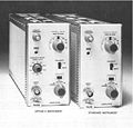
7a29 manual photo.jpg | photo of 7A29 from manual (normal and option 4 units) | |||
</gallery> | </gallery> | ||
== | ====Internal==== | ||
<gallery> | <gallery> | ||
7a29 left.jpg | 7A29, left side | |||
Tek 7a29 left.jpg | 7A29 Opt.4, left view (variable delay line enclosure above PCB) | |||
7a29 right.jpg | 7A29, right side | |||
7a29 protection relay 1.jpg | 7A29 input protection relay | |||
7a29 protection relay lever.jpg | 7A29 input protection relay lever | |||
7a29 conn.jpg | 7A29 backplane connector (stripline signal path) | |||
Tek 7a29 amps.jpg | 7A29 amplifiers | |||
Tek 7a29 right rear.jpg | 7A29, right side, rear | |||
Tek 7a29 right front.jpg | 7A29, right side, front | |||
</gallery> | |||
====Schematics==== | |||
<gallery> | |||
7a29 input amp schem.png | input amplifier schematic | |||
7a29 output amp schem.png | output amplifier schematic | |||
</gallery> | |||
====Measurements==== | |||
<gallery> | |||
7a29-rise.jpg | Sample 7A29 rise time measurement (Source: [[S-52]]) - 320 ps equiv. 1.09 GHz system bandwidth including [[7104]] mainframe | |||
</gallery> | </gallery> | ||
[[Category:7000 series vertical plugins]] | [[Category:7000 series vertical plugins]] | ||
Revision as of 11:28, 18 September 2017
Template:Plugin Sidebar 2 The Tektronix 7A29 is a 1 GHz single-channel vertical plug-in for 7000-series scopes. It is primarily intended for the 7103 and 7104. Like with the 7A19, a variable signal delay was available as an option.
There is also a 7A29P, which has digitally programmable gain, intended for the 7000 series digitizers and the 7854 only.
The 7F10 uses the 7A29's amplifier board after the optical/electrical converter.
Key Specifications
| Bandwidth | 1 GHz (in 7104) |
|---|---|
| Input impedance | 50±1 Ω, VSWR <1.2:1 from DC to 1 GHz (10 mV/Div: 1.4:1, Opt.4: 1.5:1) |
| Max. input | max. 10 VRMS or 1 Ws pulses not exceeding 50 V; max. 100 V additional DC component in AC mode |
| Deflection | 10 mV/div to 1 V/div, 1-2-5, ±2%; variable 2.5:1 |
| Channels | Single channel |
| Recommended probes | P6056 (×10), P6057 (×100) |
| Options | Option 4: variable delay (1 ns) |
Internals
The 7A29 employs a number of Tek-made custom Hypcon-packaged hybrids, the 155-0180-00 fast input protection, 155-0181-00 input amplifier and 155-0175-00 trigger amplifier (2 ×).
It uses a "feed-beside" scheme implemented with standard low-frequency operational amplifiers to compensate for low-frequency anomalies in the frequency response that are attributed to transistor heating.
The input connector is a special Tek-made part that is exactly 50 Ω. Typical BNC connectors are around 52 Ω.
Links
- Tektronix 7A29 teardown - nice detailed pictures of attenuator internals
- Tek 7A29P @ amplifier.cd including internal pictures
Pictures
-
7A29 (no opt.) front
-
7A29 Opt.4 front
-
7A29P
-
photo of 7A29 from manual (normal and option 4 units)
Internal
-
7A29, left side
-
7A29 Opt.4, left view (variable delay line enclosure above PCB)
-
7A29, right side
-
7A29 input protection relay
-
7A29 input protection relay lever
-
7A29 backplane connector (stripline signal path)
-
7A29 amplifiers
-
7A29, right side, rear
-
7A29, right side, front
Schematics
-
input amplifier schematic
-
output amplifier schematic


