585: Difference between revisions
No edit summary |
No edit summary |
||
| Line 48: | Line 48: | ||
==Pictures== | ==Pictures== | ||
==585 non-A== | |||
<gallery> | |||
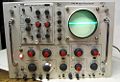
Tek 585 with 82.jpg|585 with [[82]] | |||
Tek585-bottom.jpg | Bottom | |||
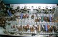
Tek585-dl-driver-1.jpg | Delay line driver amplifier | |||
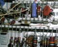
Tek585-dl-driver-bot.jpg | Delay line driver amplifier (bottom) | |||
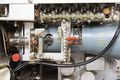
Tek585-left-1.jpg | Left side | |||
Tek585-vert-1.jpg | Vertical amplifier (post-delay 5-stage distributed amplifier) | |||
Tek585-vert-2.jpg | Vertical amplifier (5-stage dist amp, power output stage) | |||
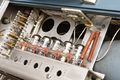
Tek585-rect.jpg | Rectifiers | |||
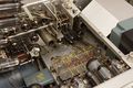
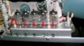
Tek585-tb-a.jpg | Time Base A | |||
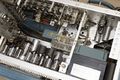
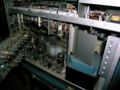
Tek585-top-1.jpg |Top view | |||
</gallery> | |||
==585A== | |||
<gallery> | <gallery> | ||
Tek 585a trace.jpg | Tek 585a trace.jpg | ||
585a_front.jpg|585A with [[82]] | 585a_front.jpg|585A with [[82]] | ||
585a_trig.jpg|585A trigger circuit | 585a_trig.jpg|585A trigger circuit | ||
| Line 56: | Line 70: | ||
585a_door_open.jpg|Inside view shows regulator tubes | 585a_door_open.jpg|Inside view shows regulator tubes | ||
585a_dist_vert amp.jpg|Distributed vertical amplifier | 585a_dist_vert amp.jpg|Distributed vertical amplifier | ||
T580_CRT.JPG|[[T581]]0P31 distributed deflection plates | T580_CRT.JPG|[[T581]]0P31 distributed deflection plates | ||
Wellenkino 585a 2.jpg | Wellenkino 585a 2.jpg | ||
Wellenkino 585A.jpg | Wellenkino 585A.jpg | ||
585a_delay1.jpg|585A delay line | 585a_delay1.jpg|585A delay line | ||
585_delay2.jpg|585A delay line | 585_delay2.jpg|585A delay line | ||
| Line 66: | Line 78: | ||
Tek 585a sine trace.jpg | Tek 585a sine trace.jpg | ||
Tek 585a square trace.jpg | Tek 585a square trace.jpg | ||
Tek 585 upgraded to 585a.jpg|585 with TRIGGER SOURCE switch upgraded to 585A design | Tek 585 upgraded to 585a.jpg|585 with TRIGGER SOURCE switch upgraded to 585A design | ||
Tek 585a right internal on cart.jpg|585A on cart | Tek 585a right internal on cart.jpg|585A on cart | ||
Tek 585a with 81a and hickok plugin.jpg|585A with [[81|81A]] and Hickok plug-in | Tek 585a with 81a and hickok plugin.jpg|585A with [[81|81A]] and Hickok plug-in | ||
Tek 585a handbook.jpg | |||
Tek 58x direct crt.png|Direct Connection to CRT (from 1964 Service Scope) | |||
</gallery> | |||
==RM585A== | |||
<gallery> | |||
Rm 585a.jpg|RM-585A | |||
</gallery> | </gallery> | ||
[[Category:580 series scopes]] | [[Category:580 series scopes]] | ||
Revision as of 10:17, 8 April 2018

The Tektronix 585 is a 100 MHz 580-Series scope introduced by Tektronix in 1959 and made through the 1960s. (The 585A was discontinued after 1971.)
Key Specifications
- please add
Internals
Plug-in Interface
The 585 uses 580-series plug-ins, which look like letter-series and 1-series plug-ins but are electrically different, primarily in the impedance of the signal interface between the plug-in and the scope. The pin-out is also different: it's essentially flipped 180° from its 530/540/550 series counterparts. 'Signal out' is on 14/16 as opposed to 1/3, etc...
The Type 81 adapter allows the use of letter-series and 1-series plug-ins in a 585.
Trigger Circuit
The original 585 (up to serial number 1070) has an "A" trigger circuit that has a differential trigger amplifier made of a pair of 6EW6 miniature pentodes, followed by a Schmitt trigger made of a pair of miniature dual triode tubes.
Starting at serial number 1071, the miniature dual triode Schmitt trigger was replaced by a 10 mA tunnel diode and a pulse amplifier made with an OC171 germanium PNP transistor. The tunnel diode is AC-coupled to the base-emitter junction of the transistor.
Vertical Signal Path
Like the 545, 551, and 555, the 585 uses a distributed amplifier for vertical deflection. Unlike the other 500-series scopes, the 585 uses a CRT with distributed vertical deflection plates, the T581, enabling it to have both high sensitivity and fast risetime. Total CRT acceleration voltage is 10 kV.
Several improvements were published for the 585 circuitry, including the enhanced trigger circuit. If all of those changes are applied to a 585, it is essentially a 585A.
Rackmount Versions
Rackmount versions were also made, the RM585 and RM585A.
Pictures
585 non-A
-
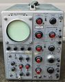
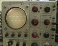
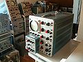
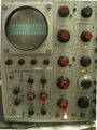
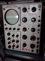
585 with 82
-
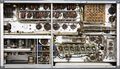
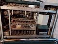
Bottom
-
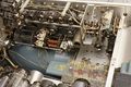
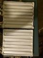
Delay line driver amplifier
-
Delay line driver amplifier (bottom)
-
Left side
-
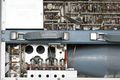
Vertical amplifier (post-delay 5-stage distributed amplifier)
-
Vertical amplifier (5-stage dist amp, power output stage)
-
Rectifiers
-
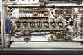
Time Base A
-
Top view


585A
-
-
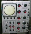
585A with 82
-
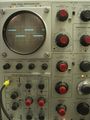
585A trigger circuit
-
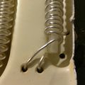
White plastic clip holds tunnel diode for triggering
-
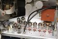
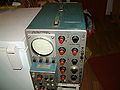
Inside view shows regulator tubes
-
Distributed vertical amplifier
-

T5810P31 distributed deflection plates
-
-
-
585A delay line
-
585A delay line
-
585A delay line
-
-
-
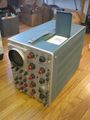
585 with TRIGGER SOURCE switch upgraded to 585A design
-
585A on cart
-
585A with 81A and Hickok plug-in
-
-
Direct Connection to CRT (from 1964 Service Scope)


RM585A
-
RM-585A
