570: Difference between revisions
No edit summary |
No edit summary |
||
| Line 10: | Line 10: | ||
|designers=John Kobbe | |designers=John Kobbe | ||
|manuals= | |manuals= | ||
* [[Media:070-167.pdf|Tektronix 570 Manual 070-167]] ( | * [[Media:070-167.pdf|Tektronix 570 Manual 070-167]] (OCR, good quality) | ||
* [[Media:070-359.pdf|Tektronix 570 Manual 070-359 (1963)]] ( | * [[Media:070-359.pdf|Tektronix 570 Manual 070-359 (1963)]] (good quality) | ||
* [https://w140.com/mmm/tek-570.pdf Tektronix 570 Manual (mediocre quality | <!-- * [https://w140.com/mmm/tek-570.pdf Tektronix 570 Manual] (mediocre quality) --> | ||
* [https://w140.com/tek_fcp/tek_570_fac_cal.pdf | <!-- * [https://w140.com/tek_fcp/tek_570_fac_cal.pdf 570 Factory Calibration Procedure 1959] --> | ||
* [[Media:Tek 570 fcp feb 1964.pdf| | <small> | ||
* [[Media:Tek 570 fcp | '''Calibration''' | ||
* [[Media:Tek 570 fcp feb 1964.pdf|570 Factory Calibration Procedure 1964]] | |||
* [[Media:Tek 570 fcp.pdf|570 Factory Calibration Procedure 1959]] | |||
</small> | |||
}} | }} | ||
The '''Tektronix 570''' was Tek's first curve tracer. It is a curve tracer for tubes | The '''Tektronix 570''' was Tek's first curve tracer, [[introduced in 1955]]. It is a curve tracer for vacuum tubes. | ||
It sweeps the plate voltage between zero and a selectable maximum voltage while "stepping" the control grid through a set of voltages. | It sweeps the plate voltage between zero and a selectable maximum voltage while "stepping" the control grid through a set of voltages. | ||
A selectable screen voltage is available for testing tubes with screens. | A selectable screen voltage is available for testing tubes with screens. | ||
The plate voltage is measured and applied to the X-axis of the display. | The plate voltage is measured and applied to the X-axis of the display. | ||
Plate current is measured and amplified and is applied to the Y-axis of the display. | Plate current is measured and amplified and is applied to the Y-axis of the display. | ||
[[John Kobbe]] had a key role in the development of both the 570 and [[575]] curve tracers. | |||
{{MissingSpecs}} | {{MissingSpecs}} | ||
| Line 43: | Line 47: | ||
A [[T0520|T52P1]] CRT is standard in the 570. | A [[T0520|T52P1]] CRT is standard in the 570. | ||
==Links== | |||
* https://vintagetek.org/curve-tracers/ | |||
* [[Media:Tek 570 10 amp request.pdf|Request from GE for a 10-amp 570]] (1961) | |||
==Pictures== | ==Pictures== | ||
Revision as of 16:12, 13 August 2023

The Tektronix 570 was Tek's first curve tracer, introduced in 1955. It is a curve tracer for vacuum tubes. It sweeps the plate voltage between zero and a selectable maximum voltage while "stepping" the control grid through a set of voltages.
A selectable screen voltage is available for testing tubes with screens. The plate voltage is measured and applied to the X-axis of the display. Plate current is measured and amplified and is applied to the Y-axis of the display.
John Kobbe had a key role in the development of both the 570 and 575 curve tracers.
Key Specifications
- please add
Internals
The 570 contains five transformers:
- T310: center-tapped isolation transformer for plate sweep
- T340: multitap transformer for heater voltages
- T401: multitap autotransformer for selecting peak plate voltage, feeds T310
- T501: transformer for floating supplies and screen voltage supply
- T620: transformer for 60 kHz HV power oscillator for CRT voltages
The screen supply is regulated and uses a 6CD6GA tube as the series regulator.
The vertical and horizontal amplifiers are almost identical. The first stage is a differential amplifier made of two 6AU6 tubes. The second stage is a differential amplifier made of both halves of a 6BQ7A.
A T52P1 CRT is standard in the 570.
Links
Pictures
Early Tektronix 570 (Brown Era)


Tektronix 570 Serial Number 5010


Tektronix 570 Serial Number 5055


Tektronix 570 Serial Number 5148


Tektronix 570 Serial Number 5429


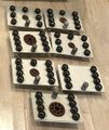
Adaptors for Different Tube Bases
-
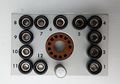
12-pin adaptor
-
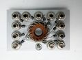
12-pin adaptor
-

7-pin miniature adaptor
-
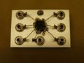
7-pin miniature adaptor
-