TM506: Difference between revisions
m (070-6929-00.pdf uploaded, needed removed) |
No edit summary |
||
| Line 10: | Line 10: | ||
The '''TM506A''' is an updated variant, [[introduced in 1989]], that essentially looks exactly the same as the [[TM5006]], i.e. it is taller, has air outlets on the front and a flip switch instead of a pull switch. | The '''TM506A''' is an updated variant, [[introduced in 1989]], that essentially looks exactly the same as the [[TM5006]], i.e. it is taller, has air outlets on the front and a flip switch instead of a pull switch. | ||
==Options== | {{BeginSpecs}} | ||
{{Spec | Power | 100/110/120/200/220/240 V<sub>AC</sub>, 48 to 60 Hz, max. 320 W }} | |||
{{EndSpecs}} | |||
The TM506 supplies five unregulated voltages to the plug-in modules: | |||
* +33.5 V, 350 mA max, common to all plug-in slots | |||
* −33.5 V, 350 mA max, common to all plug-in slots | |||
* +11.5 V, 1.3 A max in regular compartment, 4 A max in high-power compartment; common to regular plug-in slots, floating on high-power slot | |||
* 2 × 25 V<sub>AC</sub>, 2 x 0.5 A / 25 VA (combined) max in regular compartment, 60 VA (combined) max in high-power compartment; floating ≤350 V (peak) per plug-in | |||
* 17.5 V<sub>AC</sub> with grounded center tap, 30 VA max in standard compartment, 95 VA max in high-power compartment; common to regular plug-in slots, floating on high-power slot | |||
<small> | |||
===Options=== | |||
'''Option 2''' | |||
Option 2 adds internal pin headers for each slot as well as rear 50-pin and BNC connectors, allowing for custom wiring to, from and between plugins. | Option 2 adds internal pin headers for each slot as well as rear 50-pin and BNC connectors, allowing for custom wiring to, from and between plugins. | ||
On the TM506, the rear connectors are installed in an additional rear plate which is mounted adjacent to the fan shroud. | On the TM506, the rear connectors are installed in an additional rear plate which is mounted adjacent to the fan shroud. | ||
'''Option 7''' | |||
From the manual: | From the manual: | ||
| Line 23: | Line 33: | ||
<blockquote>The following described bus wires and keys are added to the connector boards of the TM 500-Series Power Module to provide rear interface connections between the TM 500 Counters containing Option 7, the [[TR502]], and the [[SW503]].</blockquote> | <blockquote>The following described bus wires and keys are added to the connector boards of the TM 500-Series Power Module to provide rear interface connections between the TM 500 Counters containing Option 7, the [[TR502]], and the [[SW503]].</blockquote> | ||
===Bus Wires=== | |||
Six-conductor ribbon cable (Tektronix Part No. [[175-0829-00]]) is used to make bus runs between the following points: | Six-conductor ribbon cable (Tektronix Part No. [[175-0829-00]]) is used to make bus runs between the following points: | ||
| Line 34: | Line 44: | ||
A18 on J10, J20, and J30 | A18 on J10, J20, and J30 | ||
===Barrier Keys=== | |||
From the manual: | From the manual: | ||
<blockquote>Plastic barrier keys (Tektronix Part No. [[214-1593-02]]) are inserted between pins 21 and 22 on J10 between pins 23 and 24 on J20 and between pins 17 and 18 on J30.<br> | <blockquote>Plastic barrier keys (Tektronix Part No. [[214-1593-02]]) are inserted between pins 21 and 22 on J10 between pins 23 and 24 on J20 and between pins 17 and 18 on J30.<br> | ||
Once the above bus connections are made and barrier keys inserted, the three connectors so changed are system dedicated and the three slots should only be used for system-dedicated plug-ins.</blockquote> | Once the above bus connections are made and barrier keys inserted, the three connectors so changed are system dedicated and the three slots should only be used for system-dedicated plug-ins.</blockquote> | ||
</small> | |||
==Links== | ==Links== | ||
| Line 58: | Line 61: | ||
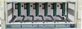
Tek tm506 1.jpg | TM506 Front | Tek tm506 1.jpg | TM506 Front | ||
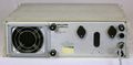
Tek tm506 2.jpg | TM506 Rear | Tek tm506 2.jpg | TM506 Rear | ||
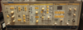
TM506 Option 7.jpg | TM506 Option 7 | TM506 Option 7.jpg | TM506 Option 7 | ||
Tek tm506 rtm506 pinout.png | Interface Connector Pinout | Tek tm506 rtm506 pinout.png | Interface Connector Pinout | ||
| Line 64: | Line 66: | ||
Tek tm506 rtm506 power supply.png | Power Supply | Tek tm506 rtm506 power supply.png | Power Supply | ||
</gallery> | </gallery> | ||
===RTM506=== | |||
<gallery> | |||
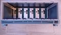
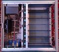
TM506_open1.jpg | |||
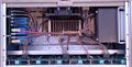
TM506-rear.jpg | RTM506 Rear | |||
</gallery> | |||
===TM506A=== | ===TM506A=== | ||
<gallery> | <gallery> | ||
Revision as of 03:46, 4 December 2023

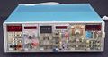
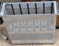
The Tektronix TM506 is a six-bay mainframe for the TM500 system. The rightmost compartment can supply high-powered plugins.
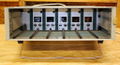
The RTM506 is the electrically identical rack-mount version, with a 14 W fan in place of the 7 W fan used in the TM506.
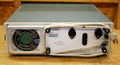
The TM506A is an updated variant, introduced in 1989, that essentially looks exactly the same as the TM5006, i.e. it is taller, has air outlets on the front and a flip switch instead of a pull switch.
Key Specifications
| Power | 100/110/120/200/220/240 VAC, 48 to 60 Hz, max. 320 W |
|---|
The TM506 supplies five unregulated voltages to the plug-in modules:
- +33.5 V, 350 mA max, common to all plug-in slots
- −33.5 V, 350 mA max, common to all plug-in slots
- +11.5 V, 1.3 A max in regular compartment, 4 A max in high-power compartment; common to regular plug-in slots, floating on high-power slot
- 2 × 25 VAC, 2 x 0.5 A / 25 VA (combined) max in regular compartment, 60 VA (combined) max in high-power compartment; floating ≤350 V (peak) per plug-in
- 17.5 VAC with grounded center tap, 30 VA max in standard compartment, 95 VA max in high-power compartment; common to regular plug-in slots, floating on high-power slot
Options
Option 2
Option 2 adds internal pin headers for each slot as well as rear 50-pin and BNC connectors, allowing for custom wiring to, from and between plugins.
On the TM506, the rear connectors are installed in an additional rear plate which is mounted adjacent to the fan shroud.
Option 7
From the manual:
The following described bus wires and keys are added to the connector boards of the TM 500-Series Power Module to provide rear interface connections between the TM 500 Counters containing Option 7, the TR502, and the SW503.
Bus Wires
Six-conductor ribbon cable (Tektronix Part No. 175-0829-00) is used to make bus runs between the following points:
TM 506
B14 on J10, J20, and J30
B15 on J10, J20, and J30
B16 on J10, J20, and J30
B17 on J10, J20, and J30
B18 on J10, J20, and J30
A18 on J10, J20, and J30
Barrier Keys
From the manual:
Plastic barrier keys (Tektronix Part No. 214-1593-02) are inserted between pins 21 and 22 on J10 between pins 23 and 24 on J20 and between pins 17 and 18 on J30.
Once the above bus connections are made and barrier keys inserted, the three connectors so changed are system dedicated and the three slots should only be used for system-dedicated plug-ins.
Links
Pictures
TM506
-
-
TM506 Front
-
TM506 Rear
-
TM506 Option 7
-
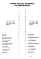
Interface Connector Pinout
-
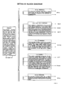
Block Diagram
-
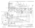
Power Supply


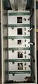
RTM506
-
-
RTM506 Rear


TM506A
-
TM506A
-
TM506A Front
-
TM506A with Hitachi plugins
-
TM506A Open
-
TM506A Power Supply
-
TM506A Rear


Pulse Instruments MOD-DP-16


Components
Some Parts Used in the TM506
| Part | Part Number(s) | Class | Description | Used in |
|---|---|---|---|---|
| 2N3055 | 151-0140-00 | Discrete component | general-purpose silicon NPN power transistor | TM504 • TM506 • TM5006 • 7603 • 7613 • 7623 • 7623A • 7623B • 7633 |