SW503

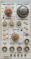
The Tektronix SW503 is a sweep generator plug-in for the TM500 system.
It provides a swept frequency of 1 MHz to 400 MHz with variable sweep rate, width, and output level. Crystal-controlled harmonic oscillators provide comb markers with 1 MHz, 10 MHz, or 50 MHz separation. When used with a DC502 Option 7 counter, a frequency marker dot can be positioned anywhere within the frequency range of the SW503, and the frequency of the marker can be read directly on the counter.
Key Specifications
| Frequency range | 1 to 400 MHz |
|---|---|
| Sweep width | 200 kHz to 400 MHz |
| Sweep time | 10 ms to 100 s, decade steps plus vernier |
| Output | −40 to +10 dBm into 50 Ω |
| Horizontal output | 0.5 Vp-p |
| Fixed markers | frequency comb with 1, 10, or 50 MHz base frequency |
| Variable marker | 1 to 400 MHz, digital readout on a DC502 Opt.07 or DC508/DC508A Opt.07 counter |
| Features |
|
| Options |
|
Links
Documents Referencing SW503
Internals
A control voltage tunes a sweep oscillator from 1001 MHz to 1400 MHz. This frequency is mixed with a fixed 1 GHz signal to produce the 1 MHz to 400 MHz output. A 50 MHz oscillator with ÷5 and ÷10 dividers drives a step-recovery diode at the selected marker frequency to generate a frequency comb. This is mixed with a sample of the sweep frequency to generate a series of zero beats that are detected and superimposed on the detector input signal for the V display output.
A comparator stops the sweep integrator when the control voltage reaches the level set by the DOT POSITION control. At this point, the Start Count line (rear interface B18) signals the counter to start counting, which sets the counter /GATE signal (rear interface A18) low. When the count is complete, /GATE goes high again, which causes the sweep to resume.
The Rear Interface manual says,
Other counters could be modified by the user to work with the dot marker scheme.
Only two of the lines are required, the start count (18Β) to trigger the counter, and the negative gate (18Α) from the counter to resume the sweep.
In addition, contact 17Β[1] would have to be grounded on the sweep generator.
- ↑ Incorrectly identified as 16B in manual
Rear Interface
| Connector Pin | Signal |
|---|---|
| 28B | Y axis output (common on 28A) |
| 27B | X axis output (common on 27A) |
| 24B | Trigger input (common on 25B) |
| 21B | Amplitude control input (0 – 10 V), common on 22B |
| 20B | Frequency control input (0 – 10 V), common on 22B |
| 18B | Start Count (0/+5 V; positive pulse to trigger the counter) |
| 18A | Gate (0/+5 V; negative gate from counter) |
| 17B | Counter Identify (grounded when counter is installed) |
| 16B | Phase Lock Logic (grounded by the SW503) |
| 15B | CW Mode Logic (+5 V: dot marker function; 0 V: normal counter function) |
| 14B | Sweep Generator Identify (grounded by the SW503) |
Pictures
External
-
-
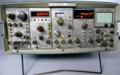
SW503 in TM515 with other TM500 gear
-
-


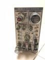
SW503 Opt.1


SW503B
-
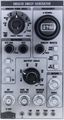
SW503B catalog picture

Internal


Components
Some Parts Used in the SW503
- (no results)