3A74: Difference between revisions
No edit summary |
No edit summary |
||
| Line 45: | Line 45: | ||
==Links== | ==Links== | ||
* [http://www.amplifier.cd/Test_Equipment/Tektronix/Tektronix_other/3A74.htm Tek 3A74 @ amplifier.cd] | * [http://www.amplifier.cd/Test_Equipment/Tektronix/Tektronix_other/3A74.htm Tek 3A74 @ amplifier.cd] | ||
* [http://www.barrytech.com/tektronix/vintage/tek3a74.html Tek 3A74 @ barrytech.com] | * [https://web.archive.org/web/20221204160652/http://www.barrytech.com/tektronix/vintage/tek3a74.html Tek 3A74 @ barrytech.com (waybackarchive)] | ||
* [https://www.radiomuseum.org/r/tektronix_3a74_plug_in_unit.html Tek 3A74 @ radiomuseum.org] | * [https://www.radiomuseum.org/r/tektronix_3a74_plug_in_unit.html Tek 3A74 @ radiomuseum.org] | ||
Latest revision as of 02:22, 21 December 2024
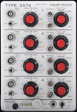
The Tektronix 3A74 is a four-channel vertical plug-in introduced in 1963 for 560-series scopes. Bandwidth is DC to 2 MHz.
A modified 3A74/MOD730A (with a charge pre-amplifier on channel 1 to accommodate piezoelectric pressure transducers) was part of the Engine Analyzer System.
Key Specifications
| Bandwidth | 2 MHz |
|---|---|
| Input impedance | 1 MΩ // 47 pF |
| Deflection | 20 mV/Div to 10 V/Div in 1–2–5 sequence |
| Features |
|
Links
Documents Referencing 3A74
| Document | Class | Title | Authors | Year | Links |
|---|---|---|---|---|---|
| 070-0890-00.pdf | Manual | Engine Analyzer System | 1968 | Engine Analyzer System • 561B • 564B • 3A74 • 2B67 • 015-0108-00 | |
| Tekscope 1969 V1 N2 Apr 1969.pdf | Article | A New Insight Into Reciprocating Machinery | Bill Verhoef | 1969 | Engine Analyzer System • 3A74 • 561B • 564B |
Internals
Each input signal passes through switchable input attenuators and then into a cathode-follower made from a 7586 Nuvistor triode driving a PNP differential amplifier. The output of this differential amplifier, for each of the four channels, passes through a diode-based analog signal switching network (multiplexer). The output of that multiplexer drives the output amplifier, which is part transistor, part tube. The one-hot select line signals for the multiplexer are generated by a transistor-based ring oscillator, a four-state cyclic state machine. This allows each of the input signals to be traced on the screen, one after another.
The 3A74 uses Tek-made 185 Ω potentiometers in for the VAR GAIN controls. These can be a maintenance issue.
The 3A74 contains a total of eight 7586 Nuvistors.
Links
Pictures
US-Made Version
-
-
Front Side
-
Rear Side
-
Left Side
-
Right Side
-
Block Diagram
-
Channel Switching
-
Amplifier
-
VAR GAIN potentiometer, sometimes problematic
-
-
-
-
-
-
-
-
-
-
-
-
3A74 Engine Analyzer Amplifier (note CH1 calibrated in PSI/div)
Netherlands-Made Version
Components
Some Parts Used in the 3A74
| Part | Part Number(s) | Class | Description | Used in |
|---|---|---|---|---|
| 6CL6 | 154-031 • 154-0031-00 • 154-0286-00 | Vacuum Tube (Pentode) | 7.5 W power pentode | 132 • 310 • 310A • 316 • 317 • 515 • 524 • 525 • 531 • 535 • 535A • 545 • 545A • 545B • 549 • 570 • 581 • 581A • 585 • 585A • 3A74 |
| 7586 | 154-0306-00 | Vacuum Tube (Triode) | Nuvistor triode | M • 1A1 • 1A2 • 1A5 • 10A2 • 10A2A • 11B1 • 11B2A • 321 • 321A • 3A1 • 3A1S • 3A3 • 3A5 • 3A6 • 3A7 • 3A8 • 3A74 • 3S76 • 3T77 • 3T77A • 3B5 • 4S1 • 4S2 • 6R1 • 6R1A • 9A1 • 9A2 • 82 • 86 • S-311 |


