7844
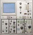
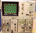
The Tektronix 7844 is a 400 MHz dual-beam CRT oscilloscope that takes two 7000-series vertical plug-ins and two 7000-series horizontal plug-ins. Circuit design for the 7844 was done by Chuck Scott, Dick Anderson, Keith Taylor, and Bob White.
Versions include the 7844 bench-top lab scope and R7844 rack-mount model.
A typical configuration might have included 7A19 or 7A24 amplifiers, 7B80/7B85 or 7B92A timebases.
Key Specifications
| Bandwidth | 400 MHz with 7A19, 7A29 (eq. 0.9 ns rise time), 300 MHz with 7A24 |
|---|---|
| Fastest calibrated sweep | 1 ns (with 7B80, 7B85, 7B92A) |
| Beam isolation | > 100:1 from DC to 150 MHz, > 30:1 from 150 MHz to 400 MHz |
| X-Y Phase Shift | < 2° from DC to min. 50 kHz |
| Horizontal bandwidth | DC to at least 1 MHz |
| Z axis input | 2 Vp-p for full intensity range (positive decreases), input impedance 500 Ω, rise time 15 ns, max. 1 MHz |
| CRT | T7840, p/n 154-0713-00 with P31 phosphor, or 154-0713-04 with P11 phosphor (Opt. 78), acceleration 24 kV (−3/+21) |
| Calibrator | 4 mV, 40 mV, 400 mV or 4 V into >100 kΩ, 0.4 mV, 4 mV, 40 mV or 400 mV into 50 Ω; 1 kHz |
| Power | 90-132 V or 180-264 V, 48 to 440 Hz, max. 235 W |
| Weight | 16.3 kg (36 lbs) / R7844: 15 kg (33 lbs) |
Internals
The 7844's CRT has distributed vertical deflection plates. It uses a number of custom ICs, such as 155-0064-00, 155-0065-00 and 155-0059-00 in the vertical amplifiers, 155-0095-00 in the vertical interface, 155-0078-00 in the trigger selector, and 155-0022-00 in the horizontal interface. The horizontal and Z axis amplifiers are discrete.
The 7844 is more complex than all other 7000 mainframes except the 7854 because vertical and horizontal amplifiers as well as the Z axis control boards exist twice, and there is an extra switching logic board. As a consequence, verifying correct operation requires testing many possible combinations of settings – for example, a defect on the vertical switching board could cause a problem only in the case of both beam 1 and 2 using horizontal bay B, but not if beam 1 used A and beam 2 used B. Moreover, calibration and adjustment is significantly more work than in a single-beam scope, e.g. CRT geometry trimpots need to be adjusted for matching both beams, not only for best geometry, and these adjustments even interact slightly.
The power supply is a resonant switch-mode inverter with linear post-regulation, similar to the one in the 7904. It uses the 155-0067-02 controller. Despite having an SMPS, the 7844 is fairly heavy behause of the duplicate internal components, especially the second vertical delay line. The delay lines need extra space and are located vertically to the right of the CRT instead of below the CRT as in other 7xx4s.
Unlike some other 7000 series mainframes with switch mode PSUs, the 7844 does have a fan.
Links
- A 400 MHz dual-beam oscilloscope. Tekscope Vol.6 No.4, Sept/Oct 1974
- Tek 7844 page at amplifier.cd and a repair report (switch-mode PSU)
- Tek 7844 @ barrytech.com
- R7844 page with frequency response measurements
- Tek R7844 page @ EB5AGV, lots of internal photos
Prices
| Year | 1976 | 1980 | 1984 | 1990 (7844R) | |
|---|---|---|---|---|---|
| Mainframe only | Catalog price | $6,100 | $9,125 | $13,435 | $19,500 |
| 2018 value | $26,690 | $27,570 | $32,200 | $37,150 | |
| Mainframe with 2 × 7A19, 7B85, 7B80 |
Catalog price | $9,500 | $14,275 | $21,520 | $30,660 |
| 2019 value | $41,570 | $43,140 | $51,570 | $58,410 |
Pictures
-
Tektronix 7844 front view
-
Tektronix 7844 rear view
-
Tektronix R7844
-
Tektronix R7844, rear view
-
7844 with options 78 (blue P11 phosphor) and 21 (dedicated vertical slots, i.e. no vertical mode switch)
-
-
-
-
Interior
-
Right interior. Top row: Calibrator board (l), readout board (c), beam 2 horizontal amplifier (r), fan.
-
Right/above interior. The dual delay lines can be seen behind the readout board. Horizontally mounted boards in the center are: Crossover mode switch (l), trigger selector (c), power supply (r).
-
Beam 2 vertical amplifier, CRT and termination detail (right side)
-
Left interior. Beam 1 vertical amplifier (l), crossover vertical interface (r).
-
Left/above interior. Top row: Beam 1 Z axis (l), Beam 1 / Beam 2 horizontal amplifiers (c/r).
-
Vertical mode switch board, back side
-
Vertical mode switch board, back side (detail)


