P6046: Difference between revisions
(rename cat) |
No edit summary |
||
| (8 intermediate revisions by 3 users not shown) | |||
| Line 1: | Line 1: | ||
{{Probe Sidebar | |||
|manufacturer=Tektronix | |||
|model=P6046 | |||
|summary=100 MHz differential probe | |||
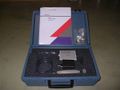
|image=Tek P6046 catalog 2.jpg | |||
|caption=Tektronix P6046 Differential Probe and 015-0106-00 Amplifier | |||
|for=50 Ω scope inputs | |||
|introduced=1968 | |||
|discontinued=1992 | |||
|designers=Glenn Bateman | |||
|manuals= | |||
There are three versions of the manual: | |||
* [[Media:070-0756-00.pdf|070-0756-00 - 1968]] − assumes [[1A5]] for absolute gain calibration | |||
* [[Media:070-7129-00.pdf|070-7129-00 - 1988]] | |||
* [[Media:070-7129-01.pdf|070-7129-01 - 1992]] | |||
* [[Media:P6046 Voltage and Waveform Information.pdf|P6046 Voltage and Waveform Information]] | |||
* [[Media:P6046 Schematics Rev. C June 1977 11x17.pdf|P6046 Schematics Rev. C June 1977]] | |||
* [[Media:Tek p6046 eis signature page.pdf|P6046 Engineering Instrument Specification Signature Page]] | |||
* [[Media:Tek p6046 fcp march 1968.pdf|P6046 Factory Calibration Procedure, March 1968]] | |||
}} | |||
The '''Tektronix P6046''' is a 100 MHz differential probe oscilloscope probe [[introduced in 1968]] and discontinued sometime after 1992. | |||
It was designed by [[Glenn Bateman]]. | |||
It was initially intended for use with a [[1A5|1A5 plug-in]], to which it attaches through a 9-pin [[Amphenol 165 series connector]]. | |||
A separate amplifier (015-0106-00) was available as an option to use the probe on a 50 Ω input scope set at 10 mV/Div. | |||
An additional ×10 attenuator (010-0361-00) can be plugged onto the P6046's inputs. | |||
( | |||
Note that the probe itself acts as either a 1× or 10× attenuation probe dependent on a signal voltage on pin D of the connector. | |||
When used with the amplifier, 10× mode is used in the 200, 100, and 50 mV/div settings and 1× mode for 20, 10, 5, 2, and 1 mV/div. | |||
{{BeginSpecs}} | |||
{{Spec | Bandwidth | 45 MHz with 1A5; 100 MHz with amplifier; AC low frequency cut-off 20 Hz (2 Hz with ×10 head) }} | |||
{{Spec | Input impedance | 1 MΩ // 10 pF (with ×10 head, 10 MΩ // 3 pF) }} | |||
( | {{Spec | Common-mode range | ±5 V DC+peak AC up to 10 MHz, decreasing to ±2 V at 50 MHz }} | ||
{{Spec | Maximum Allowable Input | 25 V total DC+peak AC, 25 V total difference between + and − input tips }} | |||
{{EndSpecs}} | |||
==Operation== | |||
== | |||
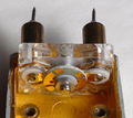
The two probe tips are (in DC mode) directly connected to the gates of a pair of JFETs. | |||
Use the shorting plugs on the tips when not in use: | |||
<blockquote>Ground the probe! Seriously. Sticker the probe "Ground Me!" I also recommend stickering the probe amplifier with the ATTEN BAL setup procedure from section 2-6 of the manual.</blockquote> | |||
==Links== | ==Links== | ||
* [http://www.i9t.net/p6046/p6046.html P6046 @ iceNINE Tech] | * [http://www.i9t.net/p6046/p6046.html P6046 @ iceNINE Tech] | ||
* [ | * [https://www.amplifier.cd/Test_Equipment/Tektronix/Tektronix_other/P6046.htm P6046 @ amplifier.cd] | ||
{{Documents|Link=P6046}} | |||
==Pictures== | ==Pictures== | ||
<gallery> | <gallery> | ||
P6046_1.jpg | P6046 | |||
P6046_2.jpg | P6046 | |||
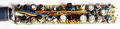
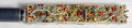
Tek p6046 internal1.jpg | Tek p6046 internal1.jpg | ||
Tek p6046 internal2.jpg | Tek p6046 internal2.jpg | ||
Latest revision as of 06:14, 28 January 2024

The Tektronix P6046 is a 100 MHz differential probe oscilloscope probe introduced in 1968 and discontinued sometime after 1992. It was designed by Glenn Bateman.
It was initially intended for use with a 1A5 plug-in, to which it attaches through a 9-pin Amphenol 165 series connector.
A separate amplifier (015-0106-00) was available as an option to use the probe on a 50 Ω input scope set at 10 mV/Div.
An additional ×10 attenuator (010-0361-00) can be plugged onto the P6046's inputs.
Note that the probe itself acts as either a 1× or 10× attenuation probe dependent on a signal voltage on pin D of the connector. When used with the amplifier, 10× mode is used in the 200, 100, and 50 mV/div settings and 1× mode for 20, 10, 5, 2, and 1 mV/div.
Key Specifications
| Bandwidth | 45 MHz with 1A5; 100 MHz with amplifier; AC low frequency cut-off 20 Hz (2 Hz with ×10 head) |
|---|---|
| Input impedance | 1 MΩ // 10 pF (with ×10 head, 10 MΩ // 3 pF) |
| Common-mode range | ±5 V DC+peak AC up to 10 MHz, decreasing to ±2 V at 50 MHz |
| Maximum Allowable Input | 25 V total DC+peak AC, 25 V total difference between + and − input tips |
Operation
The two probe tips are (in DC mode) directly connected to the gates of a pair of JFETs.
Use the shorting plugs on the tips when not in use:
Ground the probe! Seriously. Sticker the probe "Ground Me!" I also recommend stickering the probe amplifier with the ATTEN BAL setup procedure from section 2-6 of the manual.
Links
Documents Referencing P6046
| Document | Class | Title | Authors | Year | Links |
|---|---|---|---|---|---|
| Service Scope 46 Oct 1967.pdf | Article | P6046 DC-to-100 MHz Differential Probe and Amplifier | Glenn Bateman | 1967 | P6046 |
| Tekscope 1972 V4 N5 Sep 1972.pdf | Article | A Practical Approach to Differential Amplifiers and Measurements | Fred Beckett | 1972 | 112 • 11A33 • 1A5 • 1A6 • 1A7 • 1A7A • 26A2 • 3A9 • 5A22N • 7A13 • 7A22 • AM502 • D • E • G • P6055 • P6046 • W • Z |
| Tekscope 1972 V4 N6 Nov 1972.pdf | Article | Differential Amplifiers and Measurements, Part 2 | Fred Beckett | 1972 | 112 • 11A33 • 1A5 • 1A6 • 1A7 • 1A7A • 26A2 • 3A9 • 5A22N • 7A13 • 7A22 • AM502 • D • E • G • P6055 • P6046 • W • Z |
Pictures
-
P6046
-

P6046
-
-
-
-
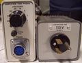
015-0106-00 amplifier and power supply


