211

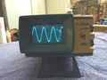
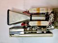
The Tektronix 211 is a 500 kHz single-channel miniaturized analog battery-powered oscilloscope. The 1 MΩ input probe is directly wired to the instrument. External trigger and horizontal inputs are provided via banana jack. The 211 "Miniscope" was developed by a group led by Dave Allen.
Key Specifications
| Bandwidth | DC to 500 kHz (100 kHz at 1 mV/div) |
|---|---|
| Input Impedance | 1 MΩ // 130 pF |
| Input Voltage | max. 600 V DC + peak AC, or 600 Vp-p AC |
| Sweep Range | 200 ms to 5 μs per division |
| CRT | 154-0642-00 (<B080000) or 154-0699-00, 6(V) × 10(H) |
| Battery Runtime | 3-5 Hours with maximum intensity |
| Battery | 10 rechargeable NiCd cells |
| Line Voltage | 110-126V AC ±10%, 58−62 Hz |
| Power Consumption | < 2 W @ 126 VAC, 60 Hz |
| Dimensions | (H/W/D) 3" × 5.2" × 8.9" (7.6 cm x 13.2 cm x 22.6 cm) |
| Weight | 3 lbs/1.38 kg |
Internals
Vertical
The probe input first goes through compensated attenuators and then into one gate of Q18, a dual JFET. The drains of the dual JFET drive the inputs of dual output amplifier IC U25, part number 155-0057-00. U25 drives one section of dual output amplifier U105 155-0047-00 which drives CRT V-plates via output transistors Q110/Q107.
Horizontal
Triggering is done using U65 155-0048-01, which contains a horizontal amplifier (for external), trigger, and sweep generator. The output of U65 drives the second section of dual output amplifier IC U25 155-0057-00 whose output is fed to the H-plates via output transistors Q119/Q122. U65 is mounted on the input board. The unblanking signal from U65 is driven to CRT via Q134.
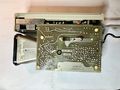
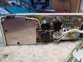
Power Supply
Tek 211 can be operated from line power or the internal Ni-Cd battery. Line power is also used for charging the batteries. Internally the unit uses a DC-DC converter to generate the required voltages from the battery or line, using Q242, Q249, and T250. DC-DC converter generates the +5.6 V, -5.6 V, and +65 V used in the unit. -1 kV for CRT is generated using a voltage multiplier.
Instead of the transformer, a capacitive divider is used to step-down down the line voltage. C210 is the capacitor for providing charging voltage and C212 gets parallel to C210 for line operation. The value of these capacitors needs to be adjusted based on operating line frequency and voltage. Manual suggests recommended values of these capacitors for common line frequency and voltages. Input AC must be sinusoidal to offer the correct reactance to step-down the line voltage.
Like other instruments of the era, there are no filter capacitors in the power supply, rather the battery is used as the filter capacitor. Hence disconnecting the battery can affect the unit's operation.
Background
Regarding his experience as a Tektronix manufacturing engineer for the CRTs for the Miniscope series (211, 212, 213, and 214), Dale Dorando recalls:
I worked under Bill Johnson, one of the manufacturing managers, especially the flood guns used in the storage CRT's. I was the weld lab manager too. We designed, tested, selected electrodes, and weld settings for the elements inside the CRT.
The CRT division had a great concept where the new engineers work at each station for a week or two learning all the processes and actually making parts. The side advantage is you meet the production people and when you need something you know who to ask.
The CRTs for the 211, 212, 213, and the storage version, 214, were manufactured using a pilot program where the same assembler worked on all phases of the tube. The other CRT's were being built by a person that only did one portion of the assembly. As an example, the deflection plates were assembled and carefully aligned, the next operator may not realize that and if accidentally bent, tried to bend them back. Naturally they wouldn't be properly aligned. By having the same people perform every process, they could see what was important and what could be improved. The primary goal was to find ways to improve the processes. By performing all the steps it was easier to find these improvements. The result was that with just these four operators, the yield and volume for the Miniscope CRT became much higher than the conventional CRTs.
The cathode for the Miniscope CRT was a critical part of the design. It took several tries to get that right. It was being done in conjunction with our partner, Sony. Sony was to use the same 1/4 watt cathode in the Trinitron TV. The cathode was a direct heated type - the filament and cathode were on the same flat wire. This reduced the power necessary to heat the cathode to the required temperature. This was important for a battery operated device. The spacing between the cathode and the grid with extremely important for the intensity and spot size. If the filament deformed while being heated, the cathode could move. The filament had springs that kept it taught across a ceramic ring inside the grid cup. The cathode was a small disk with the triple carbonate coating blown on to the surface at a precise thickness.
As with most of the Tektronix CRTs, it used deflection blanking where the beam is aimed off the screen during the horizontal retrace. This was faster and easier to control with the associated electronics than changing the negative high voltage with respect to the grid.
Glass rods hold the elements in place inside the CRT. Having so many elements embedded in such a small glass rod made them fragile. The rodding process was carefully controlled for temperature and time.
The bulb of the CRT was ceramic with an internal gold plating as the anode. The bulb was frit-bonded at high temperatures to the glass neck. The faceplate was also frit-bonded to the ceramic bulb. The faceplate was first silkscreened with the graticule. After the faceplate was bonded to the bulb, the phosphor was allowed to settle in a liquid onto the faceplate. The liquid was poured out and then aluminum pellets were evaporated on to the phosphor in a mild vacuum. The aluminum helped resist burning the phosphor and reflected the light from the back to the front for a brighter sweep.
The electron gun was welded to the stem with the pins. That was inserted into the neck, that was previously bonded to the ceramic bulb, and using a lathe with a torch, melted the stem to the neck. The CRT was evacuated and the metals inductively heated to remove the gasses in the metal, then sealed. The getter was inductively flashed to a size dictated by a template for that CRT. The larger the flash, the better is absorbed the impurities, but too much flashing could short out metal parts.
A coil was wound around the CRT to allow for a trace rotation adjustment in the oscilloscope. This would correct for any small gun rotational alignment.
See Also
Prices
| Year | 1973 |
|---|---|
| Catalog Price | $545 |
| In 2023 Dollars | $3,800 |
Pictures
-
-
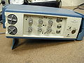
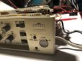
211 Front view
-
211 RHS
-
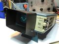
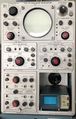
211 with Viewing Hood Part 016-0199-00
-
-
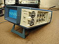
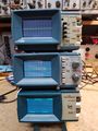
Size comparison, 211 vs. 555
-
211 Battery charge meter
-
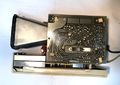
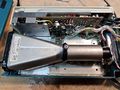
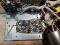
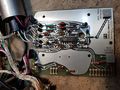
211 Internal top
-
211 Top w/o amplifier board
-
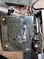
211 Internal bottom
-
211 Internal bottom w/o PS board
-
211 Internal LHS
-
Input Board (rear)
-
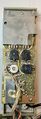
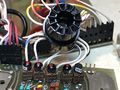
Tek 211 Input board (rear)
-
Input board front (w/o front panel)
-
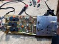
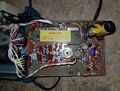
Amplifier board
-
Amplifier board
-
Amplifier board (trace side)
-
Power supply board
-
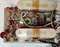
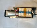
Power supply board and battery
-
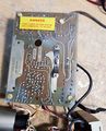
Power supply board (trace side)
-
Output transistors
-
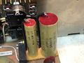
Dropping caps in power supply
-
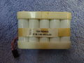
Tek 211 internal battery pack


Components
Some Parts Used in the 211
| Part | Part Number(s) | Class | Description | Used in |
|---|---|---|---|---|
| 154-0642-00 | 154-0642-00 | CRT | CRT for miniature scopes | 211 |
| 154-0699-00 | 154-0699-00 • 154-0699-50 | CRT | directly-heated CRT for miniature scopes | 211 • 212 • SC501 |
| 155-0047-00 | 155-0047-00 | Monolithic integrated circuit | dual variable-gain amplifier | 211 • 212 • 214 |
| 155-0048-01 | 155-0048-00 • 155-0048-01 • 155-0055-00 • 155-0055-01 | Monolithic integrated circuit | trigger sweep | 211 • 212 • 213 • 214 • 432 • 433 • 5B12N • 5B13N • 5L4N • 603 • 604 • 605 • 606 • 606A • 607 • 624 • SC501 • R7912 |
| 155-0057-00 | 155-0057-00 | Monolithic integrated circuit | amplifier | 211 |